Cisco 2948G Hardware Installation Guide - Page 58
Attaching the L Brackets, Installing the Switch
 |
UPC - 746320228884
View all Cisco 2948G manuals
Add to My Manuals
Save this manual to your list of manuals |
Page 58 highlights
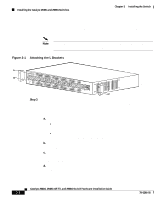
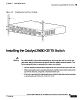
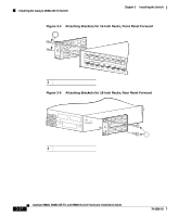
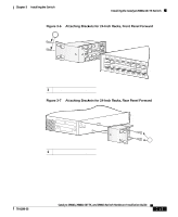
Installing the Catalyst 2948G and 2980G Switches Chapter 3 Installing the Switch The L brackets connect the switch chassis to the rack. You can mount the L brackets to the front- or rear-mounting holes of the chassis, depending on which end is in the front of the rack. Note The Catalyst 2948G switch is shown in the rack-mounting illustrations. The rack-mounting procedure for the Catalyst 2980G switch is the same. Figure 3-1 Attaching the L Brackets 98435 STATUS Catalyst 2948G CONSOLE 1000Base - X 10BaseT Step 3 Figure 3-2 shows how to attach the front of the switch to the rack. You can also attach the rear of the switch to the rack, depending on the configuration of your rack. Install the chassis in the rack as follows: a. Position the switch chassis in the rack (see Figure 3-2): • If the chassis front panel is to be in the front of the rack, insert the rear of the chassis between the mounting posts. • If the rear of the chassis is to be in the front of the rack, insert the front of the chassis between the mounting posts. b. Align the mounting holes in the L bracket with the mounting holes in the equipment rack. c. Secure the chassis using six 12-24 x 3/4-inch screws (three per side) through the elongated holes in the L bracket and into the threaded holes in the mounting post. d. Use the tape measure and level to ensure that the chassis is installed straight and level. Catalyst 2984G, 2948G-GE-TX, and 2980G Switch Hardware Installation Guide 3-8 78-6286-05
-
 1
1 -
2
-
3
-
4
-
5
-
6
-
7
-
8
-
9
-
10
-
11
-
12
-
13
-
14
-
15
-
16
-
17
-
18
-
19
-
20
-
21
-
22
-
23
-
24
-
25
-
26
-
27
-
28
-
29
-
30
-
31
-
32
-
33
-
34
-
35
-
36
-
37
-
38
-
39
-
40
-
41
-
42
-
43
-
44
-
45
-
46
-
47
-
48
-
49
-
50
-
51
-
52
-
 53
53 -
 54
54 -
 55
55 -
 56
56 -
 57
57 -
 58
58 -
 59
59 -
 60
60 -
 61
61 -
 62
62 -
 63
63 -
64
-
65
-
66
-
67
-
68
-
69
-
70
-
71
-
72
-
73
-
74
-
75
-
76
-
77
-
78
-
79
-
80
-
81
-
82
-
83
-
84
-
85
-
86
-
87
-
88
-
89
-
90
-
91
-
92
-
93
-
94
-
95
-
96
-
97
-
98
-
99
-
100
-
101
-
102
-
103
-
104
-
105
-
106
-
107
-
108
-
109
-
110
-
111
-
112
-
113
-
114
-
115
-
116
-
117
-
118
-
119
-
120
-
121
-
122
-
123
-
124
-
125
-
126
-
127
-
128
-
129
-
130
-
131
-
132
-
133
-
134
-
135
-
136
-
137
-
138
-
139
-
140
-
141
-
142
 |
 |
