Cisco 2948G Hardware Installation Guide - Page 40
The Catalyst 2948G switch uses the Cisco RPS 600 AC power supply - dc
 |
UPC - 746320228884
View all Cisco 2948G manuals
Add to My Manuals
Save this manual to your list of manuals |
Page 40 highlights
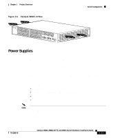
Switch Components Chapter 1 Product Overview • The Catalyst 2948G switch uses the Cisco RPS 600 AC power supply (PWR600-AC-RPS-CAB). The Cisco RPS 600 supports four external devices that use up to 150 W DC each. Use a one-to-one cable (one connector at each cable end) to connect four external devices to the four DC output power modules. The power source is partially redundant. There are two AC input power modules for the Cisco RPS and one DC output power module for each external device. The AC input to the Cisco RPS is fully redundant, but the DC output to the external devices is not. Warning Attach only the Cisco RPS (model PWR600-AC-RPS) to the RPS receptacle. Statement 112 • The Catalyst 2948G-GE-TX switch uses the Cisco RPS 675 (model PWR675-AC-RPS-N1). The RPS 675 supports six external network devices and provides DC power to one failed device at a time. It automatically senses when the internal power supply of a connected device fails and provides power to that device, which prevents loss of network traffic. Warning Attach only the Cisco RPS (model PWR675-AC-RPS-N1=) to the RPS receptacle. Statement 100C • The Catalyst 2980G-A switch uses the Cisco RPS 300 (PWR300-AC-RPS-N1). The RPS 300 supports six external network devices and provides power to one failed device at a time. It automatically senses when the power supply of a connected device fails and provides the necessary power to the failed device to prevent loss of network traffic. When the internal power supply of the device has been brought up or replaced, the RPS automatically stops powering the device. Warning Attach only the Cisco RPS (model PWR300-AC-RPS-N1) to the RPS receptacle. Statement 100B 1-12 Catalyst 2984G, 2948G-GE-TX, and 2980G Switch Hardware Installation Guide 78-6286-05
-
 1
1 -
2
-
3
-
4
-
5
-
6
-
7
-
8
-
9
-
10
-
11
-
12
-
13
-
14
-
15
-
16
-
17
-
18
-
19
-
20
-
21
-
22
-
23
-
24
-
25
-
26
-
27
-
28
-
29
-
30
-
31
-
32
-
33
-
34
-
 35
35 -
 36
36 -
 37
37 -
 38
38 -
 39
39 -
 40
40 -
 41
41 -
 42
42 -
 43
43 -
 44
44 -
 45
45 -
46
-
47
-
48
-
49
-
50
-
51
-
52
-
53
-
54
-
55
-
56
-
57
-
58
-
59
-
60
-
61
-
62
-
63
-
64
-
65
-
66
-
67
-
68
-
69
-
70
-
71
-
72
-
73
-
74
-
75
-
76
-
77
-
78
-
79
-
80
-
81
-
82
-
83
-
84
-
85
-
86
-
87
-
88
-
89
-
90
-
91
-
92
-
93
-
94
-
95
-
96
-
97
-
98
-
99
-
100
-
101
-
102
-
103
-
104
-
105
-
106
-
107
-
108
-
109
-
110
-
111
-
112
-
113
-
114
-
115
-
116
-
117
-
118
-
119
-
120
-
121
-
122
-
123
-
124
-
125
-
126
-
127
-
128
-
129
-
130
-
131
-
132
-
133
-
134
-
135
-
136
-
137
-
138
-
139
-
140
-
141
-
142
 |
 |
