Cisco 2948G Hardware Installation Guide - Page 56
Installing the Catalyst 2948G and 2980G Switches, Required Installation Tools
 |
UPC - 746320228884
View all Cisco 2948G manuals
Add to My Manuals
Save this manual to your list of manuals |
Page 56 highlights
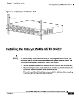
Installing the Catalyst 2948G and 2980G Switches Chapter 3 Installing the Switch Installing the Catalyst 2948G and 2980G Switches Warning To prevent bodily injury when mounting or servicing this unit in a rack, you must take special precautions to ensure that the system remains stable. The following guidelines are provided to ensure your safety: • This unit should be mounted at the bottom of the rack if it is the only unit in the rack. • When mounting this unit in a partially filled rack, load the rack from the bottom to the top with the heaviest component at the bottom of the rack. • If the rack is provided with stabilizing devices, install the stabilizers before mounting or servicing the unit in the rack. Statement 1006 A standard rack-mount kit is included for mounting the switch in a standard 19-inch (48.3 cm) equipment rack with two unobstructed outer posts. This kit is not suitable for racks with obstructions (such as a power strip) that could impair access to the switch. Required Installation Tools You will need the following tools and equipment to install the switch chassis in a rack: • Rack-mount kit • Tape measure and level • Number 1 Phillips, number 2 Phillips, or a 3/16-inch flat-blade screwdriver • Antistatic mat or antistatic foam • Your own electrostatic discharge (ESD) grounding strap or the disposable ESD strap included with the switch Note For more information about ESD, refer to the Site Preparation and Safety Guide. Catalyst 2984G, 2948G-GE-TX, and 2980G Switch Hardware Installation Guide 3-6 78-6286-05
-
 1
1 -
2
-
3
-
4
-
5
-
6
-
7
-
8
-
9
-
10
-
11
-
12
-
13
-
14
-
15
-
16
-
17
-
18
-
19
-
20
-
21
-
22
-
23
-
24
-
25
-
26
-
27
-
28
-
29
-
30
-
31
-
32
-
33
-
34
-
35
-
36
-
37
-
38
-
39
-
40
-
41
-
42
-
43
-
44
-
45
-
46
-
47
-
48
-
49
-
50
-
 51
51 -
 52
52 -
 53
53 -
 54
54 -
 55
55 -
 56
56 -
 57
57 -
 58
58 -
 59
59 -
 60
60 -
 61
61 -
62
-
63
-
64
-
65
-
66
-
67
-
68
-
69
-
70
-
71
-
72
-
73
-
74
-
75
-
76
-
77
-
78
-
79
-
80
-
81
-
82
-
83
-
84
-
85
-
86
-
87
-
88
-
89
-
90
-
91
-
92
-
93
-
94
-
95
-
96
-
97
-
98
-
99
-
100
-
101
-
102
-
103
-
104
-
105
-
106
-
107
-
108
-
109
-
110
-
111
-
112
-
113
-
114
-
115
-
116
-
117
-
118
-
119
-
120
-
121
-
122
-
123
-
124
-
125
-
126
-
127
-
128
-
129
-
130
-
131
-
132
-
133
-
134
-
135
-
136
-
137
-
138
-
139
-
140
-
141
-
142
 |
 |
