Cisco 2948G Hardware Installation Guide - Page 72
Connecting a Terminal to the Console Serial and Ethernet Management Ports - amber status light
 |
UPC - 746320228884
View all Cisco 2948G manuals
Add to My Manuals
Save this manual to your list of manuals |
Page 72 highlights
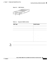
Connecting a Terminal to the Console Serial and Ethernet Management Ports Chapter 3 Installing the Switch Step 3 Step 4 Step 5 Observe the port STATUS LED: • The LED turns amber while Spanning Tree Protocol (STP) discovers the network topology and searches for loops. This process takes about 30 seconds. • The LED turns green when the switch and the target device have an established link. The LED does not light when the target device is not turned on, a cable problem exists, or a problem exists with the adapter installed in the target device. If the STATUS LED does not turn green or does not light at all, see "Troubleshooting the Installation" section on page 5-1 for solutions to cabling problems. Reconfigure and restart the target device if necessary. Repeat Steps 1 through 4 to connect each port. Connecting a Terminal to the Console Serial and Ethernet Management Ports The console serial and Ethernet management ports are located on the front panel of the Catalyst 2948G, 2948G-GE-TX, and 2980G switches. These ports use an RJ-45 media-dependent interface crossed-over (MDIX) connector, as shown in Figure 3-16. For information about port pinouts, see Appendix A, "Specifications." The Catalyst 2948G switches have a 10BASE-T management port. The Catalyst 2948G-GE-TX and 2980G-A switches have a 10/100BASE-T management port. Note The MDIX Ethernet ports are crossed over internally. For an MDI-to-MDI or MDIX-to-MDIX connection, use a crossover cable. For an MDI-to-MDIX connection, use a straight-through cable, which allows the Tx pins to connect with the Rx pins. 3-22 Catalyst 2984G, 2948G-GE-TX, and 2980G Switch Hardware Installation Guide 78-6286-05
-
 1
1 -
2
-
3
-
4
-
5
-
6
-
7
-
8
-
9
-
10
-
11
-
12
-
13
-
14
-
15
-
16
-
17
-
18
-
19
-
20
-
21
-
22
-
23
-
24
-
25
-
26
-
27
-
28
-
29
-
30
-
31
-
32
-
33
-
34
-
35
-
36
-
37
-
38
-
39
-
40
-
41
-
42
-
43
-
44
-
45
-
46
-
47
-
48
-
49
-
50
-
51
-
52
-
53
-
54
-
55
-
56
-
57
-
58
-
59
-
60
-
61
-
62
-
63
-
64
-
65
-
66
-
 67
67 -
 68
68 -
 69
69 -
 70
70 -
 71
71 -
 72
72 -
 73
73 -
 74
74 -
 75
75 -
 76
76 -
 77
77 -
78
-
79
-
80
-
81
-
82
-
83
-
84
-
85
-
86
-
87
-
88
-
89
-
90
-
91
-
92
-
93
-
94
-
95
-
96
-
97
-
98
-
99
-
100
-
101
-
102
-
103
-
104
-
105
-
106
-
107
-
108
-
109
-
110
-
111
-
112
-
113
-
114
-
115
-
116
-
117
-
118
-
119
-
120
-
121
-
122
-
123
-
124
-
125
-
126
-
127
-
128
-
129
-
130
-
131
-
132
-
133
-
134
-
135
-
136
-
137
-
138
-
139
-
140
-
141
-
142
 |
 |
