Cisco 2948G Hardware Installation Guide - Page 89
Connecting to an SFP Module Port, Troubleshooting the Installation
 |
UPC - 746320228884
View all Cisco 2948G manuals
Add to My Manuals
Save this manual to your list of manuals |
Page 89 highlights
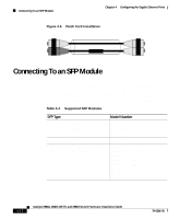
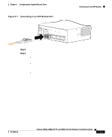
Chapter 4 Configuring the Gigabit Ethernet Ports Figure 4-7 Connecting to an SFP Module Port Connecting To an SFP Module 98656 Step 3 Step 4 Insert the other cable end in a fiber-optic receptacle on a target device. Observe the port LED. • The LED turns green when the switch and the target device have an established link. • The LED turns amber while the STP discovers the network topology and searches for loops. This process takes about 30 seconds, and then the port LED turns green. • If the LED is off, the target device might not be turned on, there might be a cable problem, or there might be problem with the adapter installed in the target device. See Chapter 5, "Troubleshooting the Installation," for solutions to cabling problems. 78-6286-05 Catalyst 2984G, 2948G-GE-TX, and 2980G Switch Hardware Installation Guide 4-15
-
 1
1 -
2
-
3
-
4
-
5
-
6
-
7
-
8
-
9
-
10
-
11
-
12
-
13
-
14
-
15
-
16
-
17
-
18
-
19
-
20
-
21
-
22
-
23
-
24
-
25
-
26
-
27
-
28
-
29
-
30
-
31
-
32
-
33
-
34
-
35
-
36
-
37
-
38
-
39
-
40
-
41
-
42
-
43
-
44
-
45
-
46
-
47
-
48
-
49
-
50
-
51
-
52
-
53
-
54
-
55
-
56
-
57
-
58
-
59
-
60
-
61
-
62
-
63
-
64
-
65
-
66
-
67
-
68
-
69
-
70
-
71
-
72
-
73
-
74
-
75
-
76
-
77
-
78
-
79
-
80
-
81
-
82
-
83
-
 84
84 -
 85
85 -
 86
86 -
 87
87 -
 88
88 -
 89
89 -
 90
90 -
 91
91 -
 92
92 -
 93
93 -
 94
94 -
95
-
96
-
97
-
98
-
99
-
100
-
101
-
102
-
103
-
104
-
105
-
106
-
107
-
108
-
109
-
110
-
111
-
112
-
113
-
114
-
115
-
116
-
117
-
118
-
119
-
120
-
121
-
122
-
123
-
124
-
125
-
126
-
127
-
128
-
129
-
130
-
131
-
132
-
133
-
134
-
135
-
136
-
137
-
138
-
139
-
140
-
141
-
142
 |
 |
