Cisco 2948G Hardware Installation Guide - Page 88
Cisco Small Form-Factor Pluggable Modules, Installation Notes, Table 4-5, Appendix A, Specifications
 |
UPC - 746320228884
View all Cisco 2948G manuals
Add to My Manuals
Save this manual to your list of manuals |
Page 88 highlights
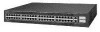
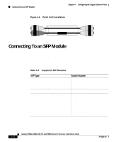
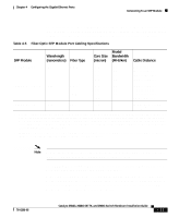
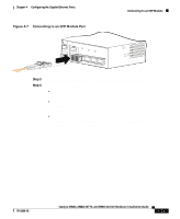
Connecting To an SFP Module Chapter 4 Configuring the Gigabit Ethernet Ports For more information about these SFP modules, refer to your SFP module documentation and to the Cisco Small Form-Factor Pluggable Modules Installation Notes (not orderable but is available on Cisco.com.) For the latest information about SFP modules supported by the switch, refer to the release notes. Caution Do not remove the rubber plugs from the ports on fiber-optic SFP modules or the rubber caps from the the fiber-optic cable until you are ready to connect the cable. The plugs and caps protect the SFP module ports and cables from contamination and ambient light. Before connecting to an SFP module, be sure that you understand the port and cabling stipulations in Table 4-5. See Appendix A, "Specifications," for information about the LC on the SFP modules for fiber-optic connections. Follow these steps to connect a fiber-optic cable to an SFP module: Warning Invisible laser radiation may be emitted from disconnected fibers or connectors. Do not stare into beams or view directly with optical instruments. Statement 272 Step 1 Step 2 Remove the rubber plugs from the module port and fiber-optic cable, and store them for future use. Insert one end of the fiber-optic cable into the SFP module port, as shown in Figure 4-7. 4-14 Catalyst 2984G, 2948G-GE-TX, and 2980G Switch Hardware Installation Guide 78-6286-05
-
 1
1 -
2
-
3
-
4
-
5
-
6
-
7
-
8
-
9
-
10
-
11
-
12
-
13
-
14
-
15
-
16
-
17
-
18
-
19
-
20
-
21
-
22
-
23
-
24
-
25
-
26
-
27
-
28
-
29
-
30
-
31
-
32
-
33
-
34
-
35
-
36
-
37
-
38
-
39
-
40
-
41
-
42
-
43
-
44
-
45
-
46
-
47
-
48
-
49
-
50
-
51
-
52
-
53
-
54
-
55
-
56
-
57
-
58
-
59
-
60
-
61
-
62
-
63
-
64
-
65
-
66
-
67
-
68
-
69
-
70
-
71
-
72
-
73
-
74
-
75
-
76
-
77
-
78
-
79
-
80
-
81
-
82
-
 83
83 -
 84
84 -
 85
85 -
 86
86 -
 87
87 -
 88
88 -
 89
89 -
 90
90 -
 91
91 -
 92
92 -
 93
93 -
94
-
95
-
96
-
97
-
98
-
99
-
100
-
101
-
102
-
103
-
104
-
105
-
106
-
107
-
108
-
109
-
110
-
111
-
112
-
113
-
114
-
115
-
116
-
117
-
118
-
119
-
120
-
121
-
122
-
123
-
124
-
125
-
126
-
127
-
128
-
129
-
130
-
131
-
132
-
133
-
134
-
135
-
136
-
137
-
138
-
139
-
140
-
141
-
142
 |
 |