Cisco 2948G Hardware Installation Guide - Page 38
Catalyst 2948G Airflow, shows the direction of airflow through the Catalyst 2948G-GE-TX - console
 |
UPC - 746320228884
View all Cisco 2948G manuals
Add to My Manuals
Save this manual to your list of manuals |
Page 38 highlights
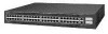
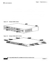
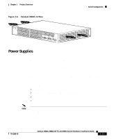
Switch Components Chapter 1 Product Overview If an individual fan fails, the other fans continue to run. Sensors monitor the internal air temperatures. If the air temperature exceeds a tolerable threshold, the environmental monitor displays warning messages. On the Catalyst 2948G-GE-TX, a blower system draws cool air in from the front and sides of the switch and exhausts air out the back. Figure 1-4 shows the direction of airflow through the Catalyst 2948G switch. Figure 1-5 shows the direction of airflow through the Catalyst 2948G-GE-TX switch. Figure 1-6 shows the direction of airflow through the Catalyst 2980G switch. Figure 1-4 Catalyst 2948G Airflow 98432 STATUS Catalyst 2948G CONSOLE 1000Base - X 10BaseT Figure 1-5 Catalyst 2948G-GE-TX Airflow 98720 1-10 Catalyst 2984G, 2948G-GE-TX, and 2980G Switch Hardware Installation Guide 78-6286-05
-
 1
1 -
2
-
3
-
4
-
5
-
6
-
7
-
8
-
9
-
10
-
11
-
12
-
13
-
14
-
15
-
16
-
17
-
18
-
19
-
20
-
21
-
22
-
23
-
24
-
25
-
26
-
27
-
28
-
29
-
30
-
31
-
32
-
 33
33 -
 34
34 -
 35
35 -
 36
36 -
 37
37 -
 38
38 -
 39
39 -
 40
40 -
 41
41 -
 42
42 -
 43
43 -
44
-
45
-
46
-
47
-
48
-
49
-
50
-
51
-
52
-
53
-
54
-
55
-
56
-
57
-
58
-
59
-
60
-
61
-
62
-
63
-
64
-
65
-
66
-
67
-
68
-
69
-
70
-
71
-
72
-
73
-
74
-
75
-
76
-
77
-
78
-
79
-
80
-
81
-
82
-
83
-
84
-
85
-
86
-
87
-
88
-
89
-
90
-
91
-
92
-
93
-
94
-
95
-
96
-
97
-
98
-
99
-
100
-
101
-
102
-
103
-
104
-
105
-
106
-
107
-
108
-
109
-
110
-
111
-
112
-
113
-
114
-
115
-
116
-
117
-
118
-
119
-
120
-
121
-
122
-
123
-
124
-
125
-
126
-
127
-
128
-
129
-
130
-
131
-
132
-
133
-
134
-
135
-
136
-
137
-
138
-
139
-
140
-
141
-
142
 |
 |
