Dell DX6004S Hardware Owner's Manual - Page 120
Installing the Power Supply Blank, Removing a Non-Redundant Power Supply
 |
View all Dell DX6004S manuals
Add to My Manuals
Save this manual to your list of manuals |
Page 120 highlights
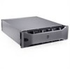
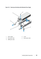
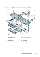
Installing the Power Supply Blank NOTE: Install the power supply blank only in power supply bay PS2. To install the power supply blank, align the blank with the power supply bay and insert the blank into the chassis until it clicks into place. Removing a Non-Redundant Power Supply CAUTION: Many repairs may only be done by a certified service technician. You should only perform troubleshooting and simple repairs as authorized in your product documentation, or as directed by the online or telephone service and support team. Damage due to servicing that is not authorized by Dell is not covered by your warranty. Read and follow the safety instructions that came with the product. 1 Turn off the system and all attached peripherals. 2 Disconnect the power cable from the power source. 3 Disconnect the power cable from the power supply and remove the Velcro straps that bundle and secure the system cables. NOTE: You may have to unlatch and lift the optional cable management arm if it interferes with power-supply removal. For information about the cable management arm, see the system's rack documentation. 4 Open the system. See "Opening the System" on page 76. 5 Disconnect all the power cables from the power supply to the system board, hard drives and optical drive. See Figure 3-19. 6 Loosen the screw securing the power supply to the chassis and lift the power supply to remove it from the chassis. See Figure 3-19. 120 Installing System Components
-
 1
1 -
2
-
3
-
4
-
5
-
6
-
7
-
8
-
9
-
10
-
11
-
12
-
13
-
14
-
15
-
16
-
17
-
18
-
19
-
20
-
21
-
22
-
23
-
24
-
25
-
26
-
27
-
28
-
29
-
30
-
31
-
32
-
33
-
34
-
35
-
36
-
37
-
38
-
39
-
40
-
41
-
42
-
43
-
44
-
45
-
46
-
47
-
48
-
49
-
50
-
51
-
52
-
53
-
54
-
55
-
56
-
57
-
58
-
59
-
60
-
61
-
62
-
63
-
64
-
65
-
66
-
67
-
68
-
69
-
70
-
71
-
72
-
73
-
74
-
75
-
76
-
77
-
78
-
79
-
80
-
81
-
82
-
83
-
84
-
85
-
86
-
87
-
88
-
89
-
90
-
91
-
92
-
93
-
94
-
95
-
96
-
97
-
98
-
99
-
100
-
101
-
102
-
103
-
104
-
105
-
106
-
107
-
108
-
109
-
110
-
111
-
112
-
113
-
114
-
 115
115 -
 116
116 -
 117
117 -
 118
118 -
 119
119 -
 120
120 -
 121
121 -
 122
122 -
 123
123 -
 124
124 -
 125
125 -
126
-
127
-
128
-
129
-
130
-
131
-
132
-
133
-
134
-
135
-
136
-
137
-
138
-
139
-
140
-
141
-
142
-
143
-
144
-
145
-
146
-
147
-
148
-
149
-
150
-
151
-
152
-
153
-
154
-
155
-
156
-
157
-
158
-
159
-
160
-
161
-
162
-
163
-
164
-
165
-
166
-
167
-
168
 |
 |