Dell DX6004S Hardware Owner's Manual - Page 124
Control Panel Assembly, Removing the Control Panel Board Assembly and the Control Panel Display Module
 |
View all Dell DX6004S manuals
Add to My Manuals
Save this manual to your list of manuals |
Page 124 highlights
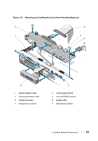
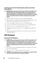
Control Panel Assembly NOTE: The LCD control panel assembly consists of two separate modules-the display module and the control panel circuit board. Use the following instructions to remove and install either module. Removing the Control Panel Board Assembly and the Control Panel Display Module CAUTION: Many repairs may only be done by a certified service technician. You should only perform troubleshooting and simple repairs as authorized in your product documentation, or as directed by the online or telephone service and support team. Damage due to servicing that is not authorized by Dell is not covered by your warranty. Read and follow the safety instructions that came with the product. 1 If applicable, remove the front bezel. See "Removing the Front Bezel" on page 75. 2 Turn off the system and attached peripherals, and disconnect the system from the electrical outlet and peripherals. 3 Open the system. See "Opening the System" on page 76. 4 Disconnect the control panel cable at the back of the control panel board. See Figure 3-21. CAUTION: Do not pull on the cable to unseat the connector. Doing so can damage the cable. 5 Press the metal tabs on the ends of the cable connector. 6 Gently work the connector out of the socket. 7 Remove the USB connector cable, the display module cable and the power cable. 8 Remove the two screws that secure the control panel board to the system chassis and remove the board. 9 Remove the two screws that secure the display module to the system chassis and remove the display module from the chassis cutout. 124 Installing System Components
-
 1
1 -
2
-
3
-
4
-
5
-
6
-
7
-
8
-
9
-
10
-
11
-
12
-
13
-
14
-
15
-
16
-
17
-
18
-
19
-
20
-
21
-
22
-
23
-
24
-
25
-
26
-
27
-
28
-
29
-
30
-
31
-
32
-
33
-
34
-
35
-
36
-
37
-
38
-
39
-
40
-
41
-
42
-
43
-
44
-
45
-
46
-
47
-
48
-
49
-
50
-
51
-
52
-
53
-
54
-
55
-
56
-
57
-
58
-
59
-
60
-
61
-
62
-
63
-
64
-
65
-
66
-
67
-
68
-
69
-
70
-
71
-
72
-
73
-
74
-
75
-
76
-
77
-
78
-
79
-
80
-
81
-
82
-
83
-
84
-
85
-
86
-
87
-
88
-
89
-
90
-
91
-
92
-
93
-
94
-
95
-
96
-
97
-
98
-
99
-
100
-
101
-
102
-
103
-
104
-
105
-
106
-
107
-
108
-
109
-
110
-
111
-
112
-
113
-
114
-
115
-
116
-
117
-
118
-
 119
119 -
 120
120 -
 121
121 -
 122
122 -
 123
123 -
 124
124 -
 125
125 -
 126
126 -
 127
127 -
 128
128 -
 129
129 -
130
-
131
-
132
-
133
-
134
-
135
-
136
-
137
-
138
-
139
-
140
-
141
-
142
-
143
-
144
-
145
-
146
-
147
-
148
-
149
-
150
-
151
-
152
-
153
-
154
-
155
-
156
-
157
-
158
-
159
-
160
-
161
-
162
-
163
-
164
-
165
-
166
-
167
-
168
 |
 |