Dell DX6004S Hardware Owner's Manual - Page 127
Press the two blue retention latches at either ends of the SAS backplane
 |
View all Dell DX6004S manuals
Add to My Manuals
Save this manual to your list of manuals |
Page 127 highlights
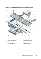
CAUTION: You must note the number of each hard drive and temporarily label them before removal so that you can replace them in the same locations. 3 Remove all hard drives. See "Removing a Hard-Drive Carrier" on page 82. 4 Disconnect the power cable from the SAS backplane. 5 Disconnect the SAS data cables from the backplane. See Figure 3-22. 6 Remove the optical drive cable, control panel cable, power cable, data cables, and USB cables. 7 Press the two blue retention latches at either ends of the SAS backplane and lift it upwards and out of the retention hooks. Be careful to avoid damaging the other components on the face of the board. See Figure 3-22. 8 Place the SAS backplane face down on a work surface. Installing System Components 127
-
 1
1 -
2
-
3
-
4
-
5
-
6
-
7
-
8
-
9
-
10
-
11
-
12
-
13
-
14
-
15
-
16
-
17
-
18
-
19
-
20
-
21
-
22
-
23
-
24
-
25
-
26
-
27
-
28
-
29
-
30
-
31
-
32
-
33
-
34
-
35
-
36
-
37
-
38
-
39
-
40
-
41
-
42
-
43
-
44
-
45
-
46
-
47
-
48
-
49
-
50
-
51
-
52
-
53
-
54
-
55
-
56
-
57
-
58
-
59
-
60
-
61
-
62
-
63
-
64
-
65
-
66
-
67
-
68
-
69
-
70
-
71
-
72
-
73
-
74
-
75
-
76
-
77
-
78
-
79
-
80
-
81
-
82
-
83
-
84
-
85
-
86
-
87
-
88
-
89
-
90
-
91
-
92
-
93
-
94
-
95
-
96
-
97
-
98
-
99
-
100
-
101
-
102
-
103
-
104
-
105
-
106
-
107
-
108
-
109
-
110
-
111
-
112
-
113
-
114
-
115
-
116
-
117
-
118
-
119
-
120
-
121
-
 122
122 -
 123
123 -
 124
124 -
 125
125 -
 126
126 -
 127
127 -
 128
128 -
 129
129 -
 130
130 -
 131
131 -
 132
132 -
133
-
134
-
135
-
136
-
137
-
138
-
139
-
140
-
141
-
142
-
143
-
144
-
145
-
146
-
147
-
148
-
149
-
150
-
151
-
152
-
153
-
154
-
155
-
156
-
157
-
158
-
159
-
160
-
161
-
162
-
163
-
164
-
165
-
166
-
167
-
168
 |
 |

Installing System Components
127
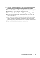
CAUTION:
You must note the number of each hard drive and temporarily label
them before removal so that you can replace them in the same locations.
3
Remove all hard drives. See "Removing a Hard-Drive Carrier" on page 82.
4
Disconnect the power cable from the SAS backplane.
5
Disconnect the SAS data cables from the backplane. See Figure 3-22.
6
Remove the optical drive cable, control panel cable, power cable, data
cables, and USB cables.
7
Press the two blue retention latches at either ends of the SAS backplane
and lift it upwards and out of the retention hooks. Be careful to avoid
damaging the other components on the face of the board. See Figure 3-22.
8
Place the SAS backplane face down on a work surface.