Dell DX6004S Hardware Owner's Manual - Page 19
Guidelines for Connecting External Devices - drivers
 |
View all Dell DX6004S manuals
Add to My Manuals
Save this manual to your list of manuals |
Page 19 highlights
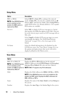
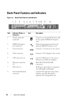
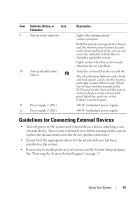
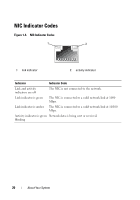
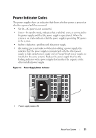
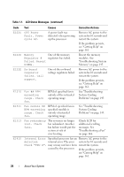
Item Indicator, Button, or Icon Connector 9 System status indicator 10 System identification button 11 Power supply 1 (PS1) 12 Power supply 2 (PS2) Description Lights blue during normal system operation. Both the systems management software and the identification buttons located on the front and back of the system can cause the indicator to flash blue to identify a particular system. Lights amber when the system needs attention due to a problem. Turns the system ID modes on and off. The identification buttons on the front and back panels can be used to locate a particular system within a rack. When one of these buttons is pushed, the LCD panel on the front and the system status indicator on the chassis back panel light blue until one of the buttons is pushed again. 400 W (redundant power supply). 400 W (redundant power supply). Guidelines for Connecting External Devices • Turn off power to the system and external devices before attaching a new external device. Turn on any external devices before turning on the system (unless the documentation for the device specifies otherwise). • Ensure that the appropriate driver for the attached device has been installed on the system. • If necessary to enable ports on your system, use the System Setup program. See "Entering the System Setup Program" on page 52. About Your System 19
-
 1
1 -
2
-
3
-
4
-
5
-
6
-
7
-
8
-
9
-
10
-
11
-
12
-
13
-
 14
14 -
 15
15 -
 16
16 -
 17
17 -
 18
18 -
 19
19 -
 20
20 -
 21
21 -
 22
22 -
 23
23 -
 24
24 -
25
-
26
-
27
-
28
-
29
-
30
-
31
-
32
-
33
-
34
-
35
-
36
-
37
-
38
-
39
-
40
-
41
-
42
-
43
-
44
-
45
-
46
-
47
-
48
-
49
-
50
-
51
-
52
-
53
-
54
-
55
-
56
-
57
-
58
-
59
-
60
-
61
-
62
-
63
-
64
-
65
-
66
-
67
-
68
-
69
-
70
-
71
-
72
-
73
-
74
-
75
-
76
-
77
-
78
-
79
-
80
-
81
-
82
-
83
-
84
-
85
-
86
-
87
-
88
-
89
-
90
-
91
-
92
-
93
-
94
-
95
-
96
-
97
-
98
-
99
-
100
-
101
-
102
-
103
-
104
-
105
-
106
-
107
-
108
-
109
-
110
-
111
-
112
-
113
-
114
-
115
-
116
-
117
-
118
-
119
-
120
-
121
-
122
-
123
-
124
-
125
-
126
-
127
-
128
-
129
-
130
-
131
-
132
-
133
-
134
-
135
-
136
-
137
-
138
-
139
-
140
-
141
-
142
-
143
-
144
-
145
-
146
-
147
-
148
-
149
-
150
-
151
-
152
-
153
-
154
-
155
-
156
-
157
-
158
-
159
-
160
-
161
-
162
-
163
-
164
-
165
-
166
-
167
-
168
 |
 |