Dell DX6004S Hardware Owner's Manual - Page 93
Installing an Expansion-Card Riser, Cooling Shroud, Removing the Cooling Shroud
 |
View all Dell DX6004S manuals
Add to My Manuals
Save this manual to your list of manuals |
Page 93 highlights
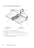
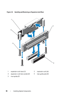
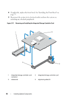
Installing an Expansion-Card Riser CAUTION: Many repairs may only be done by a certified service technician. You should only perform troubleshooting and simple repairs as authorized in your product documentation, or as directed by the online or telephone service and support team. Damage due to servicing that is not authorized by Dell is not covered by your warranty. Read and follow the safety instructions that came with the product. 1 Align the expansion-card riser with the riser guide posts on the system board. See Figure 3-9. 2 Lower the expansion-card riser into place until the expansion-card riser connector is fully seated. 3 If applicable, reinstall the expansion card. See "Installing an Expansion Card" on page 89. 4 Close the system. See "Closing the System" on page 77. 5 Reconnect the system to its electrical outlet and turn the system on, including any attached peripherals. Cooling Shroud The system board shroud covers the processor, heat sink, and memory modules, and provides air flow to these components. Airflow is facilitated by the cooling fan modules, which are positioned directly beneath the cooling shroud. The power distribution board shroud covers the power distribution board behind the power supply bay. Removing the Cooling Shroud WARNING: The memory modules and heat sink can get very hot during normal operation. Ensure that the memory modules and heat sink have had sufficient time to cool before you touch it. CAUTION: Many repairs may only be done by a certified service technician. You should only perform troubleshooting and simple repairs as authorized in your product documentation, or as directed by the online or telephone service and support team. Damage due to servicing that is not authorized by Dell is not covered by your warranty. Read and follow the safety instructions that came with the product. Installing System Components 93
-
 1
1 -
2
-
3
-
4
-
5
-
6
-
7
-
8
-
9
-
10
-
11
-
12
-
13
-
14
-
15
-
16
-
17
-
18
-
19
-
20
-
21
-
22
-
23
-
24
-
25
-
26
-
27
-
28
-
29
-
30
-
31
-
32
-
33
-
34
-
35
-
36
-
37
-
38
-
39
-
40
-
41
-
42
-
43
-
44
-
45
-
46
-
47
-
48
-
49
-
50
-
51
-
52
-
53
-
54
-
55
-
56
-
57
-
58
-
59
-
60
-
61
-
62
-
63
-
64
-
65
-
66
-
67
-
68
-
69
-
70
-
71
-
72
-
73
-
74
-
75
-
76
-
77
-
78
-
79
-
80
-
81
-
82
-
83
-
84
-
85
-
86
-
87
-
 88
88 -
 89
89 -
 90
90 -
 91
91 -
 92
92 -
 93
93 -
 94
94 -
 95
95 -
 96
96 -
 97
97 -
 98
98 -
99
-
100
-
101
-
102
-
103
-
104
-
105
-
106
-
107
-
108
-
109
-
110
-
111
-
112
-
113
-
114
-
115
-
116
-
117
-
118
-
119
-
120
-
121
-
122
-
123
-
124
-
125
-
126
-
127
-
128
-
129
-
130
-
131
-
132
-
133
-
134
-
135
-
136
-
137
-
138
-
139
-
140
-
141
-
142
-
143
-
144
-
145
-
146
-
147
-
148
-
149
-
150
-
151
-
152
-
153
-
154
-
155
-
156
-
157
-
158
-
159
-
160
-
161
-
162
-
163
-
164
-
165
-
166
-
167
-
168
 |
 |
