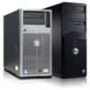
Dell PowerEdge 4100 Service Manual - Page 13
System Unit - power supply
 |
View all Dell PowerEdge 4100 manuals
Add to My Manuals
Save this manual to your list of manuals |
Page 13 highlights
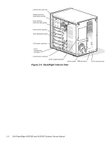
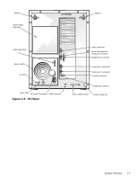
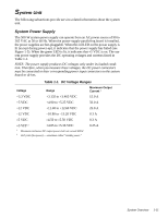
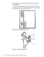
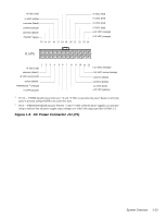
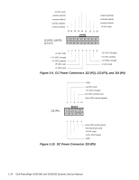
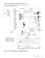
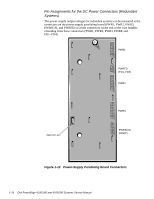
System Unit The following subsections provide service-related information about the system unit. System Power Supply The 500-W system power supply can operate from an AC power source of 90 to 265 VAC at 50 or 60 Hz. When the power-supply paralleling board is installed, the power supplies are hot-pluggable. When the red LED on the power supply is lit (except during power-up), it indicates that the power supply has failed (see Figure 1-5). When the green LED is lit, it indicates that +5 VDC is on. The system power supply provides the DC operating voltages and currents listed in Table 1-1. NOTE: The power supply produces DC voltages only under its loaded condition. Therefore, when you measure these voltages, the DC power connectors must be connected to their corresponding power input connectors on the system board or drives. . Table 1-1. DC Voltage Ranges Voltage Range Maximum Output Current 1 +3.3 VDC +3.135 to +3.465 VDC 15.0 A +5 VDC +4.90 to +5.25 VDC 50.0 A +12 VDC +11.40 to +12.60 VDC 25.0 A -12 VDC -10.80 to -13.20 VDC 0.3 A -5 VDC -4.50 to -5.50 VDC 0.3 A +5 VFP 2 +4.85 to +5.36 VDC 1 Maximum continuous DC output power shall not exceed 500 W. 2 VFP (volts flea power) - sometimes called "standby power." 0.25 A System Overview 1-11
-
 1
1 -
2
-
3
-
4
-
5
-
6
-
7
-
 8
8 -
 9
9 -
 10
10 -
 11
11 -
 12
12 -
 13
13 -
 14
14 -
 15
15 -
 16
16 -
 17
17 -
 18
18 -
19
-
20
-
21
-
22
-
23
-
24
-
25
-
26
-
27
-
28
-
29
-
30
-
31
-
32
-
33
-
34
-
35
-
36
-
37
-
38
-
39
-
40
-
41
-
42
-
43
-
44
-
45
-
46
-
47
-
48
-
49
-
50
-
51
-
52
-
53
-
54
-
55
-
56
-
57
-
58
-
59
-
60
-
61
-
62
-
63
-
64
-
65
-
66
-
67
-
68
-
69
-
70
-
71
-
72
-
73
-
74
-
75
-
76
-
77
-
78
-
79
-
80
-
81
-
82
 |
 |