Dell PowerEdge 4100 Service Manual - Page 28

Scsi2 Cd-rom.. . - specifications

Page 28 highlights

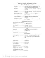
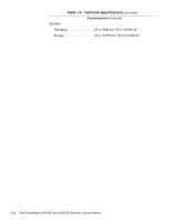
Table 1-5. Technical Specifications (continued) System Board Connectors (continued) POWER1 one 18-pin connector: standby power, I2 C, PWRGOOD, and miscellaneous power POWER2 one 20-pin connector: +3.3 VDC, +5 VDC, or +12 VDC POWER3 one 20-pin connector: +3.3 VDC, +5 VDC, or +12 VDC BACKPLANE SCSI1. . . . one 68-pin connector, ultra-wide (fast), to SCSI backplane SCSI2 CD-ROM one 50-pin connector, ultra-narrow, to CD-ROM SMB BACKPLANE. . . . . one 16-pin connector (server management) to SCSI backplane SCSI Backplane Connectors SCSI hard-disk drive connection sockets six 80-pin connectors SCSI controller one 68-pin connector Power one 14-pin connectors Video Video type embedded PCI (see User's Guide for specifications) Video memory 1 MB Key Combinations

  • 1
  • 2
  • 3
  • 4
  • 5
  • 6
  • 7
  • 8
  • 9
  • 10
  • 11
  • 12
  • 13
  • 14
  • 15
  • 16
  • 17
  • 18
  • 19
  • 20
  • 21
  • 22
  • 23
  • 24
  • 25
  • 26
  • 27
  • 28
  • 29
  • 30
  • 31
  • 32
  • 33
  • 34
  • 35
  • 36
  • 37
  • 38
  • 39
  • 40
  • 41
  • 42
  • 43
  • 44
  • 45
  • 46
  • 47
  • 48
  • 49
  • 50
  • 51
  • 52
  • 53
  • 54
  • 55
  • 56
  • 57
  • 58
  • 59
  • 60
  • 61
  • 62
  • 63
  • 64
  • 65
  • 66
  • 67
  • 68
  • 69
  • 70
  • 71
  • 72
  • 73
  • 74
  • 75
  • 76
  • 77
  • 78
  • 79
  • 80
  • 81
  • 82

1-26
Dell PowerEdge 4100/180 and 4100/200 Systems Service Manual
System Board Connectors
(continued)
POWER1 . . . . . . . . . . . . .
one 18-pin connector: standby power, I
2
C,
PWRGOOD, and miscellaneous power
POWER2 . . . . . . . . . . . . .
one 20-pin connector: +3.3 VDC, +5 VDC, or
+12 VDC
POWER3 . . . . . . . . . . . . .
one 20-pin connector: +3.3 VDC, +5 VDC, or
+12 VDC
BACKPLANE SCSI1. . . .
one 68-pin connector, ultra-wide (fast), to
SCSI backplane
SCSI2 CD-ROM. . . . . . . .
one 50-pin connector, ultra-narrow, to
CD-ROM
SMB BACKPLANE. . . . .
one 16-pin connector (server management) to
SCSI backplane
SCSI Backplane Connectors
SCSI hard-disk drive connection
sockets . . . . . . . . . . . . . . . . . .
six 80-pin connectors
SCSI controller. . . . . . . . . . . .
one 68-pin connector
Power . . . . . . . . . . . . . . . . . . .
one 14-pin connectors
Video
Video type. . . . . . . . . . . . . . . .
embedded PCI (see
User’s Guide
for
specifications)
Video memory . . . . . . . . . . . .
1 MB
Key Combinations
<Ctrl><Alt><Del>
. . . . . . . . . . . .
reboots the system (if running MS-DOS)
<F2>
. . . . . . . . . . . . . . . . . . . . . . . .
starts System Setup program (during POST
only)
Controls and Indicators
Reset control. . . . . . . . . . . . . .
push button
Power control . . . . . . . . . . . . .
push button
Power indicator. . . . . . . . . . . .
green LED
Diskette drive access
indicator . . . . . . . . . . . . . . . . .
green LED
CD-ROM busy indicator . . . .
green LED
SCSI hard-disk drive online
indicator . . . . . . . . . . . . . . . . .
green LED
Table 1-5.
Technical Specifications
(continued)