Dell PowerEdge 4100 Service Manual - Page 82
System Setup program
 |
View all Dell PowerEdge 4100 manuals
Add to My Manuals
Save this manual to your list of manuals |
Page 82 highlights
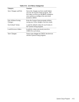
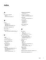
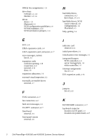
serial port connectors location on I/O panel, 1-7 location on system board, 4-17 server-management bus connector, 4-17 server-management serial port connector location on I/O panel, 1-7 location on system board, 4-17 SMB BACKPLANE connector, 4-17 sockets battery, 4-23 DIMM, 4-17, 4-19 specifications, technical, 1-24 subsystems advanced expansion, 1-8 main memory, 1-21 system board components, 4-17 illustrated, 1-20 jumpers, 1-21 location, 1-5 removing and replacing, 4-24 system board jumpers, 1-21 system error messages list of, 3-3 system features, 1-1 system power supply, 1-11 System Setup program advanced menu, A-6 boot options submenu, A-5 exit menu, A-10 key functions, A-2 main menu, A-3 menus, A-1 screen color combinations, A-3 screen conventions, A-1 security menu, A-8 starting, A-1 system specifications, 1-24 system unit cover, 4-2 T technical specifications, 1-24 termination jumpers SCSI drives, 1-10 troubleshooting boot routine, interpreting, 2-3 external visual inspection, 2-2 initial procedures, 2-1 initial user contact, 2-1 internal visual inspection, 2-4 U Ultra/Narrow SCSI host adapter connector, 4-17 Ultra/Wide SCSI host adapter connector, 4- 17 user contact, initial, 2-1 V video connector location on I/O panel, 1-7 location on system board, 4-17 video controller, integrated, 1-9 visual inspection external, 2-2 internal, 2-4 4 Dell PowerEdge 4100/180 and 4100/200 Systems Service Manual
-
 1
1 -
2
-
3
-
4
-
5
-
6
-
7
-
8
-
9
-
10
-
11
-
12
-
13
-
14
-
15
-
16
-
17
-
18
-
19
-
20
-
21
-
22
-
23
-
24
-
25
-
26
-
27
-
28
-
29
-
30
-
31
-
32
-
33
-
34
-
35
-
36
-
37
-
38
-
39
-
40
-
41
-
42
-
43
-
44
-
45
-
46
-
47
-
48
-
49
-
50
-
51
-
52
-
53
-
54
-
55
-
56
-
57
-
58
-
59
-
60
-
61
-
62
-
63
-
64
-
65
-
66
-
67
-
68
-
69
-
70
-
71
-
72
-
73
-
74
-
75
-
76
-
 77
77 -
 78
78 -
 79
79 -
 80
80 -
 81
81 -
 82
82
 |
 |