Dell PowerEdge 4100 Service Manual - Page 14
Pin Assignments for the DC Power Connectors Nonredun, dant Systems
 |
View all Dell PowerEdge 4100 manuals
Add to My Manuals
Save this manual to your list of manuals |
Page 14 highlights
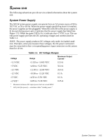
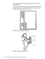
Pin Assignments for the DC Power Connectors (Nonredundant Systems) The power-supply output voltages for nonredundant systems can be measured at the connectors on the back of the power supply (P1, P2, P3, P4, and P5) or at the connectors on the power connector panel (J11, J12, J13, J14, and J15). The following illustrations show both sets of connectors. P2 P1 P5 P4 P3 Figure 1-6. Power Supply Connectors J12 (P2) J11 (P1) J15 (P5) J14 (P4) J13 (P3) Figure 1-7. Power Connector Panel 1-12 Dell PowerEdge 4100/180 and 4100/200 Systems Service Manual
-
 1
1 -
2
-
3
-
4
-
5
-
6
-
7
-
8
-
 9
9 -
 10
10 -
 11
11 -
 12
12 -
 13
13 -
 14
14 -
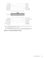 15
15 -
 16
16 -
 17
17 -
 18
18 -
 19
19 -
20
-
21
-
22
-
23
-
24
-
25
-
26
-
27
-
28
-
29
-
30
-
31
-
32
-
33
-
34
-
35
-
36
-
37
-
38
-
39
-
40
-
41
-
42
-
43
-
44
-
45
-
46
-
47
-
48
-
49
-
50
-
51
-
52
-
53
-
54
-
55
-
56
-
57
-
58
-
59
-
60
-
61
-
62
-
63
-
64
-
65
-
66
-
67
-
68
-
69
-
70
-
71
-
72
-
73
-
74
-
75
-
76
-
77
-
78
-
79
-
80
-
81
-
82
 |
 |
1-12
Dell PowerEdge 4100/180 and 4100/200 Systems Service Manual
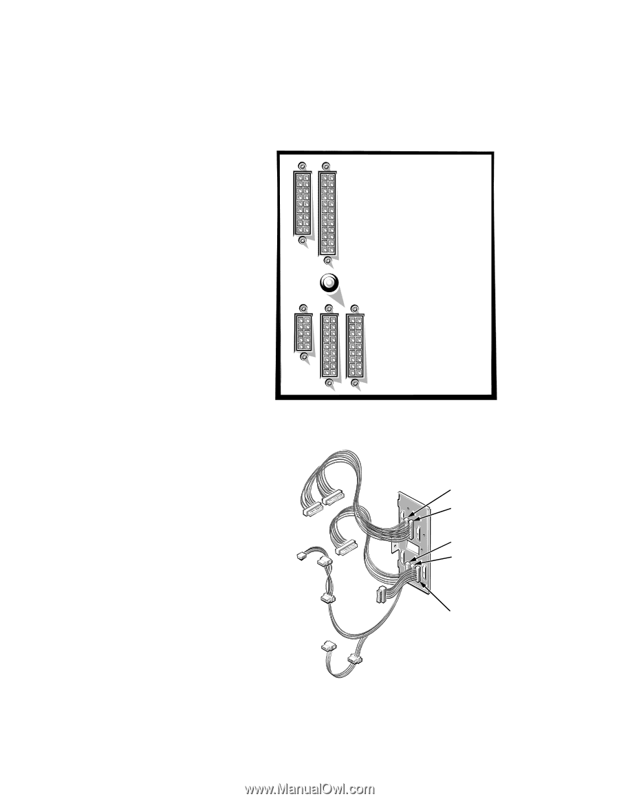
Pin Assignments for the DC Power Connectors (Nonredun-
dant Systems)
The power-supply output voltages for nonredundant systems can be measured
at the connectors on the back of the power supply (P1, P2, P3, P4, and P5) or at
the connectors on the power connector panel (J11, J12, J13, J14, and J15). The
following illustrations show both sets of connectors.
Figure 1-6.
Power Supply Connectors
Figure 1-7.
Power Connector Panel
P1
P2
P4
P3
P5
J11 (P1)
J12 (P2)
J13 (P3)
J14 (P4)
J15 (P5)