Dell PowerEdge 4100 Service Manual - Page 47
Drives
 |
View all Dell PowerEdge 4100 manuals
Add to My Manuals
Save this manual to your list of manuals |
Page 47 highlights
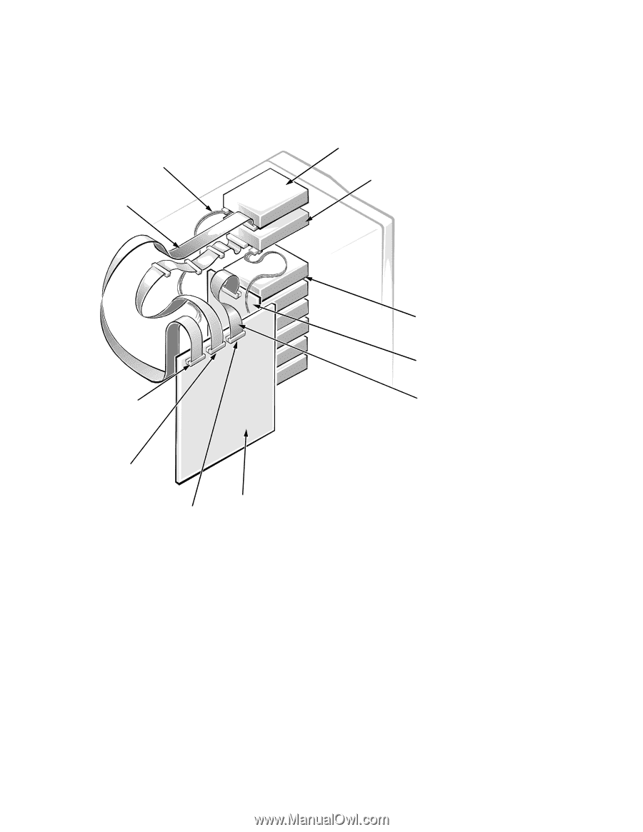
Drives Figure 4-4 shows an example of drive hardware that can be installed in the computer. Refer to this figure when you perform any of the procedures in the following subsections. DC power cable diskette/tape drive interface cable 3.5-inch diskette drive SCSI2 CD-ROM drive diskette drive interface connector (FLOPPY) SCSI connector (SCSI2 CD-ROM) SCSI connector (BACKPLANE SCSI1) Figure 4-4. Drive Hardware system board SCSI hard-disk drive bay (6) SCSI backplane board SCSI interface cable Removing and Replacing Parts 4-5
-
 1
1 -
2
-
3
-
4
-
5
-
6
-
7
-
8
-
9
-
10
-
11
-
12
-
13
-
14
-
15
-
16
-
17
-
18
-
19
-
20
-
21
-
22
-
23
-
24
-
25
-
26
-
27
-
28
-
29
-
30
-
31
-
32
-
33
-
34
-
35
-
36
-
37
-
38
-
39
-
40
-
41
-
 42
42 -
 43
43 -
 44
44 -
 45
45 -
 46
46 -
 47
47 -
 48
48 -
 49
49 -
 50
50 -
 51
51 -
 52
52 -
53
-
54
-
55
-
56
-
57
-
58
-
59
-
60
-
61
-
62
-
63
-
64
-
65
-
66
-
67
-
68
-
69
-
70
-
71
-
72
-
73
-
74
-
75
-
76
-
77
-
78
-
79
-
80
-
81
-
82
 |
 |
Removing and Replacing Parts
4-5
Drives
Figure 4-4 shows an example of drive hardware that can be installed in the com-
puter. Refer to this figure when you perform any of the procedures in the
following subsections.
Figure 4-4.
Drive Hardware
SCSI hard-disk
drive bay (6)
SCSI connector
(BACKPLANE SCSI1)
SCSI2 CD-ROM
drive
3.5-inch diskette drive
DC power cable
diskette/tape drive
interface cable
diskette drive interface
connector (FLOPPY)
SCSI interface
cable
SCSI backplane
board
system board
SCSI connector
(SCSI2 CD-ROM)