Dell PowerEdge 4100 Service Manual - Page 4
Dell PowerEdge 4100 and 6100 Systems Rack Kit Installation Guide - 200
 |
View all Dell PowerEdge 4100 manuals
Add to My Manuals
Save this manual to your list of manuals |
Page 4 highlights
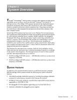
• Error correction code (ECC) feature built into the memory controller on the system board • Advanced combination EISA and PCI expansion subsystem • Five PCI and three EISA expansion-card slots (none shared) • Integrated VGA-compatible video subsystem attached to the PCI bus, with 1 MB video memory standard • BIOS in upgradable flash memory attached to the EISA bus • Integrated super I/O controller attached to the EISA bus, provides a bidirectional parallel port, two serial ports, and the diskette drive interface • Integrated ultra-wide and ultra-narrow SCSI controllers • Integrated server management circuitry that monitors critical system volt- ages and temperatures, as well as the operation of the system cooling fans • CD-ROM drive standard in an externally accessible drive bay • Recessed power and reset buttons to prevent accidental system interruptions • New quick-test feature in the system diagnostics All of these features, except the new quick-test feature, are briefly described in this chapter. (For more information about the Quick Test option in the CD-ROM based diagnostics, see "Running the System Diagnostics" in Chapter 2.) For a complete list of system features, see "Technical Specifications" found later in this chapter. For information about installing the PowerEdge 4100 systems in a rack, see the "Dell PowerEdge 4100 and 6100 Systems Rack Kit Installation Guide" (P/N 40722). 1-2 Dell PowerEdge 4100/180 and 4100/200 Systems Service Manual
-
 1
1 -
 2
2 -
 3
3 -
 4
4 -
 5
5 -
 6
6 -
 7
7 -
 8
8 -
 9
9 -
 10
10 -
11
-
12
-
13
-
14
-
15
-
16
-
17
-
18
-
19
-
20
-
21
-
22
-
23
-
24
-
25
-
26
-
27
-
28
-
29
-
30
-
31
-
32
-
33
-
34
-
35
-
36
-
37
-
38
-
39
-
40
-
41
-
42
-
43
-
44
-
45
-
46
-
47
-
48
-
49
-
50
-
51
-
52
-
53
-
54
-
55
-
56
-
57
-
58
-
59
-
60
-
61
-
62
-
63
-
64
-
65
-
66
-
67
-
68
-
69
-
70
-
71
-
72
-
73
-
74
-
75
-
76
-
77
-
78
-
79
-
80
-
81
-
82
 |
 |