Dell PowerEdge 4100 Service Manual - Page 49
Externally Accessible Drives
 |
View all Dell PowerEdge 4100 manuals
Add to My Manuals
Save this manual to your list of manuals |
Page 49 highlights
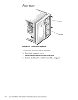
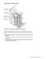
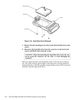
Externally Accessible Drives 3.5-inch diskette drive in top bay CD-ROM drive in middle bay lower-bay drive position for optional drive drive-release tab(2) Figure 4-6. Externally Accessible Drives Removal All of the externally accessible drives have drive-mounting rails. To remove a drive assembly from one of the externally accessible drive bays, follow these steps: 1. Disconnect the DC power cable and the interface cable from the back of the drive. Be sure to record the power connector number and interface cable connector identification. 2. Press inward (toward center of drive) on the two drive-release tabs, and slide the drive out of the bay. Removing and Replacing Parts 4-7
-
 1
1 -
2
-
3
-
4
-
5
-
6
-
7
-
8
-
9
-
10
-
11
-
12
-
13
-
14
-
15
-
16
-
17
-
18
-
19
-
20
-
21
-
22
-
23
-
24
-
25
-
26
-
27
-
28
-
29
-
30
-
31
-
32
-
33
-
34
-
35
-
36
-
37
-
38
-
39
-
40
-
41
-
42
-
43
-
 44
44 -
 45
45 -
 46
46 -
 47
47 -
 48
48 -
 49
49 -
 50
50 -
 51
51 -
 52
52 -
 53
53 -
 54
54 -
55
-
56
-
57
-
58
-
59
-
60
-
61
-
62
-
63
-
64
-
65
-
66
-
67
-
68
-
69
-
70
-
71
-
72
-
73
-
74
-
75
-
76
-
77
-
78
-
79
-
80
-
81
-
82
 |
 |
Removing and Replacing Parts
4-7
Externally Accessible Drives
Figure 4-6.
Externally Accessible Drives Removal
All of the externally accessible drives have drive-mounting rails. To remove a
drive assembly from one of the externally accessible drive bays, follow these
steps:
1.
Disconnect the DC power cable and the interface cable from the back of
the drive.
Be sure to record the power connector number and interface cable connector
identification.
2.
Press inward (toward center of drive) on the two drive-release tabs, and
slide the drive out of the bay.
drive-release
tab(2)
3.5-inch diskette
drive in top bay
CD-ROM drive in
middle bay
lower-bay drive
position for optional
drive