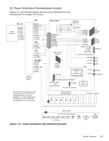
Dell PowerEdge 4100 Service Manual - Page 15
DC Power Connector J11 P1
 |
View all Dell PowerEdge 4100 manuals
Add to My Manuals
Save this manual to your list of manuals |
Page 15 highlights
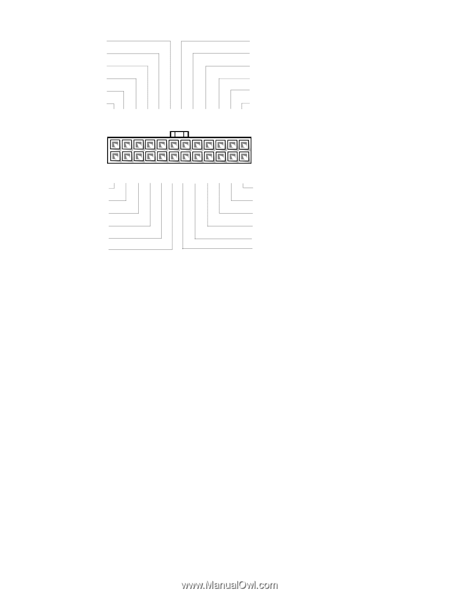
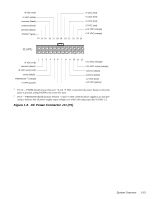
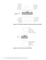
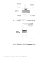
+5 VDC (red) +5 VDC (red) -5 VDC (white) common (black) +5 VDC (red) +5 VDC (red) common (black) common (black) PSON# 1(gray) +5 VDC (red) +3.3 VDC (orange) +3.3 VDC (orange) 13 14 15 16 17 18 19 20 21 22 23 24 J11 (P1) 1 2 3 4 5 6 7 8 9 10 11 12 +5 VDC (red) +3.3 VDC (orange) common (black) +3.3 VDC sense (orange) +5 VDC sense (red) common (black) -sense (black) PWRGOOD 2 (orange) +5 VFP (purple) common (black) -12 VDC (blue) +12 VDC (yellow) 1 Pin 13 - PSON# should measure between +4 and +5 VDC except when the power button on the front panel is pressed, taking PSON# to its active-low state. 2 Pin 5 - PWRGOOD should measure between +4 and +5 VDC when the power supply is on and operating to indicate that all power-supply output voltages are within the ranges specified in Table 1-1. Figure 1-8. DC Power Connector J11 (P1) System Overview 1-13
-
 1
1 -
2
-
3
-
4
-
5
-
6
-
7
-
8
-
9
-
 10
10 -
 11
11 -
 12
12 -
 13
13 -
 14
14 -
 15
15 -
 16
16 -
 17
17 -
 18
18 -
 19
19 -
 20
20 -
21
-
22
-
23
-
24
-
25
-
26
-
27
-
28
-
29
-
30
-
31
-
32
-
33
-
34
-
35
-
36
-
37
-
38
-
39
-
40
-
41
-
42
-
43
-
44
-
45
-
46
-
47
-
48
-
49
-
50
-
51
-
52
-
53
-
54
-
55
-
56
-
57
-
58
-
59
-
60
-
61
-
62
-
63
-
64
-
65
-
66
-
67
-
68
-
69
-
70
-
71
-
72
-
73
-
74
-
75
-
76
-
77
-
78
-
79
-
80
-
81
-
82
 |
 |