Dell PowerEdge 4100 Service Manual - Page 22
System Board Layout
 |
View all Dell PowerEdge 4100 manuals
Add to My Manuals
Save this manual to your list of manuals |
Page 22 highlights
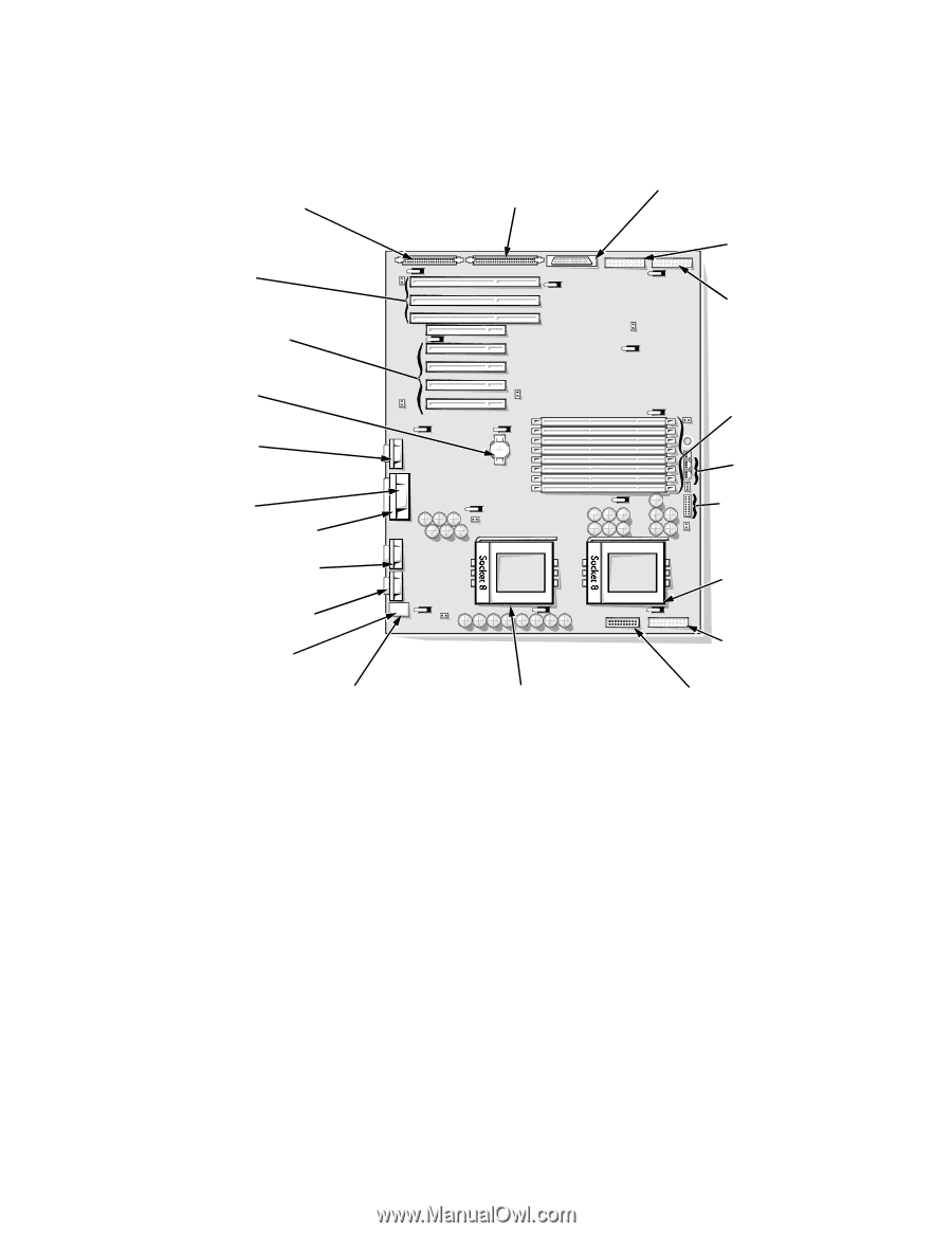
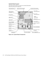
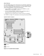
System Board Layout The subsections that follow provide service-related information about the system board components. diskette/tape drive interface Ultra/Narrow SCSI host adapter connector (FLOPPY) connector (SCSI2 CD-ROM) Ultra/Wide SCSI host adapter connector (BACKPLANE SCSI1) EISA connectors (EISA1 [top], EISA2, and EISA3) PCI connectors (PCI4 [top]-PCI8) battery connector (BATTERY) video connector (MONITOR) server-management serial port connector (REMOTE) parallel port connector (PARALLEL) serial port 2 connector (SERIAL2) serial port 1 connector (SERIAL1) mouse connector (MOUSE) keyboard connector (KEYBOARD) power supply connector (POWER2) power supply connector (POWER1) front of system board DIMM sockets (DIMM A [top]-DIMM H) fan connectors (FAN1, FAN2, FAN3) speed and configuration jumpers primary microprocessor socket (PROCESSOR1) power supply connector (POWER3) secondary microprocessor server-management bus socket (PROCESSOR2) connector (SMB BACKPLANE) Figure 1-18. System Board Components 1-20 Dell PowerEdge 4100/180 and 4100/200 Systems Service Manual
-
 1
1 -
2
-
3
-
4
-
5
-
6
-
7
-
8
-
9
-
10
-
11
-
12
-
13
-
14
-
15
-
16
-
 17
17 -
 18
18 -
 19
19 -
 20
20 -
 21
21 -
 22
22 -
 23
23 -
 24
24 -
 25
25 -
 26
26 -
 27
27 -
28
-
29
-
30
-
31
-
32
-
33
-
34
-
35
-
36
-
37
-
38
-
39
-
40
-
41
-
42
-
43
-
44
-
45
-
46
-
47
-
48
-
49
-
50
-
51
-
52
-
53
-
54
-
55
-
56
-
57
-
58
-
59
-
60
-
61
-
62
-
63
-
64
-
65
-
66
-
67
-
68
-
69
-
70
-
71
-
72
-
73
-
74
-
75
-
76
-
77
-
78
-
79
-
80
-
81
-
82
 |
 |