Dell PowerEdge 4100 Service Manual - Page 20
DC Power Connector PWRSCSI DDBP, DC Power Connector PWRFD FD1-FD4
 |
View all Dell PowerEdge 4100 manuals
Add to My Manuals
Save this manual to your list of manuals |
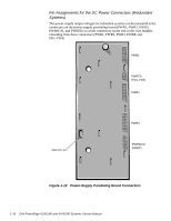
Page 20 highlights
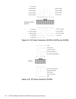
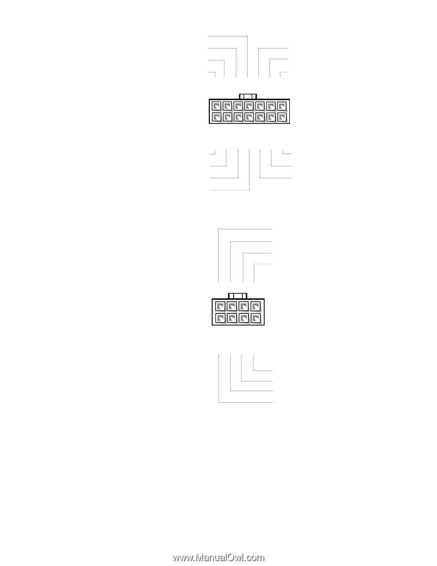
common (black) common (black) common (black) common (black) common (black) common (black) common (black) 8 9 10 11 12 13 14 PWRSCSI (DDBP) 1 23 4 +12 VDC (yellow) +5 VDC (red) +12 VDC (yellow) +5 VDC (red) 567 +12 VDC (yellow) +5 VDC (red) +12 VDC (yellow) Figure 1-15. DC Power Connector PWRSCSI (DDBP) +12 VDC (yellow) common (black) common (black) +5 VDC (red) PWRFD (FD1-FD4) 5 6 7 82 1 2 3 41 1 Wires 1 through 4 are connected to FD1 and FD2. 2 Wires 5 through 8 are connected to FD3 and FD4. +5 VDC (red) common (black) common (black) +12 VDC (yellow) Figure 1-16. DC Power Connector PWRFD (FD1-FD4) 1-18 Dell PowerEdge 4100/180 and 4100/200 Systems Service Manual
-
 1
1 -
2
-
3
-
4
-
5
-
6
-
7
-
8
-
9
-
10
-
11
-
12
-
13
-
14
-
 15
15 -
 16
16 -
 17
17 -
 18
18 -
 19
19 -
 20
20 -
 21
21 -
 22
22 -
 23
23 -
 24
24 -
 25
25 -
26
-
27
-
28
-
29
-
30
-
31
-
32
-
33
-
34
-
35
-
36
-
37
-
38
-
39
-
40
-
41
-
42
-
43
-
44
-
45
-
46
-
47
-
48
-
49
-
50
-
51
-
52
-
53
-
54
-
55
-
56
-
57
-
58
-
59
-
60
-
61
-
62
-
63
-
64
-
65
-
66
-
67
-
68
-
69
-
70
-
71
-
72
-
73
-
74
-
75
-
76
-
77
-
78
-
79
-
80
-
81
-
82
 |
 |
1-18
Dell PowerEdge 4100/180 and 4100/200 Systems Service Manual
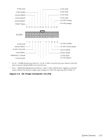
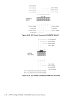
Figure 1-15.
DC Power Connector PWRSCSI (DDBP)
1
Wires 1 through 4 are connected to FD1 and FD2.
2
Wires 5 through 8 are connected to FD3 and FD4.
Figure 1-16.
DC Power Connector PWRFD (FD1–FD4)
1
2
3
4
5
6
7
+5 VDC (red)
+12 VDC (yellow)
+5 VDC (red)
+12 VDC (yellow)
PWRSCSI
(DDBP)
8
9
10
11
12
13 14
common (black)
common (black)
common (black)
common (black)
common (black)
common (black)
+12 VDC (yellow)
+5 VDC (red)
+12 VDC (yellow)
common (black)
2
3
4
1
+5 VDC (red)
PWRFD
(FD1–FD4)
1
5
6
7
8
2
+12 VDC (yellow)
common (black)
common (black)
+12 VDC (yellow)
common (black)
common (black)
+5 VDC (red)