Dell PowerEdge 4100 Service Manual - Page 18
Pin Assignments for the DC Power Connectors Redundant, Systems
 |
View all Dell PowerEdge 4100 manuals
Add to My Manuals
Save this manual to your list of manuals |
Page 18 highlights
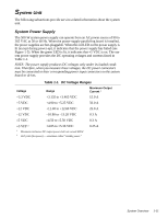
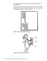
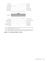
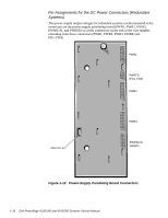
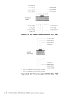
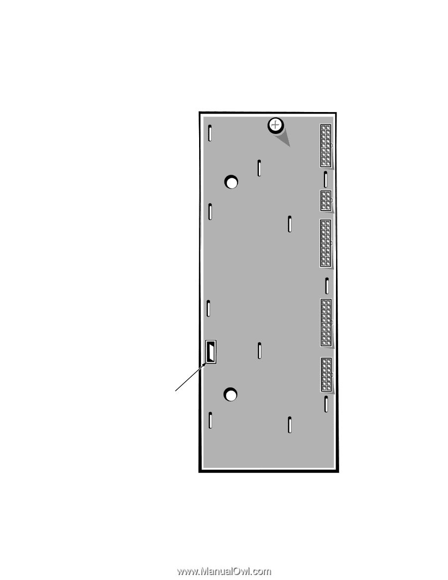
Pin Assignments for the DC Power Connectors (Redundant Systems) The power-supply output voltages for redundant systems can be measured at the connectors on the power-supply paralleling board (PWR1, PWR2, PWR3, PWRSCSI, and PWRFD) or at the connectors on the end of the wire bundles extending from these connectors (PWR1, PWR2, PWR3, DDBP, and FD1-FD4). PWR1 PWRFD (FD1-FD4) PWR2 diagnostics port PWR3 PWRSCSI (DDBP) Figure 1-12. Power-Supply Paralleling Board Connectors 1-16 Dell PowerEdge 4100/180 and 4100/200 Systems Service Manual
-
 1
1 -
2
-
3
-
4
-
5
-
6
-
7
-
8
-
9
-
10
-
11
-
12
-
 13
13 -
 14
14 -
 15
15 -
 16
16 -
 17
17 -
 18
18 -
 19
19 -
 20
20 -
 21
21 -
 22
22 -
 23
23 -
24
-
25
-
26
-
27
-
28
-
29
-
30
-
31
-
32
-
33
-
34
-
35
-
36
-
37
-
38
-
39
-
40
-
41
-
42
-
43
-
44
-
45
-
46
-
47
-
48
-
49
-
50
-
51
-
52
-
53
-
54
-
55
-
56
-
57
-
58
-
59
-
60
-
61
-
62
-
63
-
64
-
65
-
66
-
67
-
68
-
69
-
70
-
71
-
72
-
73
-
74
-
75
-
76
-
77
-
78
-
79
-
80
-
81
-
82
 |
 |
1-16
Dell PowerEdge 4100/180 and 4100/200 Systems Service Manual
Pin Assignments for the DC Power Connectors (Redundant
Systems)
The power-supply output voltages for redundant systems can be measured at the
connectors on the power-supply paralleling board (PWR1, PWR2, PWR3,
PWRSCSI, and PWRFD) or at the connectors on the end of the wire bundles
extending from these connectors (PWR1, PWR2, PWR3, DDBP, and
FD1–FD4).
Figure 1-12.
Power-Supply Paralleling Board Connectors
PWR1
PWR2
PWR3
PWRSCSI
(DDBP)
PWRFD
(FD1–FD4)
diagnostics port