Dell PowerEdge 4100 Service Manual - Page 64
Pin-1 Identification
 |
View all Dell PowerEdge 4100 manuals
Add to My Manuals
Save this manual to your list of manuals |
Page 64 highlights
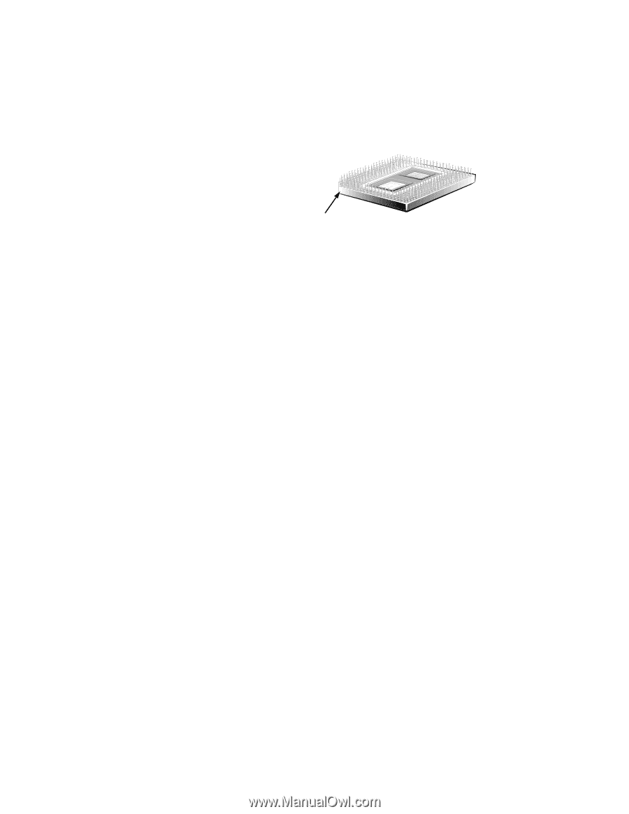
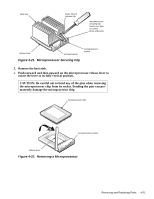
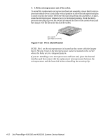
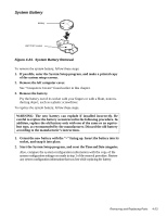
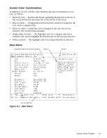
4. Lift the microprocessor out of its socket. To install the replacement microprocessor/heat sink assembly, ensure that the microprocessor release lever is in its fully vertical position to allow the microprocessor pins to easily slip into the socket. When the microprocessor/heat sink assembly is in place, rotate the microprocessor release lever to its horizontal position. Hook the microprocessor securing clip over the socket tab nearest the front of the system board, and then snap it over the tab on the back of the socket. pin-1 corner (gold finger and bevel) Figure 4-23. Pin-1 Identification NOTE: Pin 1 on the microprocessor is located on the corner with the largest bevel. The pin-1 hole in the microprocessor socket is located on the corner where the holes are in a diagonal pattern. If you are installing a new microprocessor and heat sink, place the thermal interface pad that comes with the replacement microprocessor between the microprocessor and the heat sink before reinstalling the securing clip. 4-22 Dell PowerEdge 4100/180 and 4100/200 Systems Service Manual
-
 1
1 -
2
-
3
-
4
-
5
-
6
-
7
-
8
-
9
-
10
-
11
-
12
-
13
-
14
-
15
-
16
-
17
-
18
-
19
-
20
-
21
-
22
-
23
-
24
-
25
-
26
-
27
-
28
-
29
-
30
-
31
-
32
-
33
-
34
-
35
-
36
-
37
-
38
-
39
-
40
-
41
-
42
-
43
-
44
-
45
-
46
-
47
-
48
-
49
-
50
-
51
-
52
-
53
-
54
-
55
-
56
-
57
-
58
-
 59
59 -
 60
60 -
 61
61 -
 62
62 -
 63
63 -
 64
64 -
 65
65 -
 66
66 -
 67
67 -
 68
68 -
 69
69 -
70
-
71
-
72
-
73
-
74
-
75
-
76
-
77
-
78
-
79
-
80
-
81
-
82
 |
 |