Dell PowerEdge R840 EMC Installation and Service Manual - Page 13
Rear view of the system
 |
View all Dell PowerEdge R840 manuals
Add to My Manuals
Save this manual to your list of manuals |
Page 13 highlights
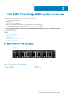
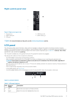
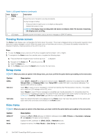
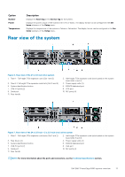
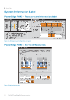
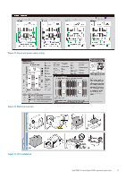
Option Number Power Temperature Description Displays the Asset tag or the Service tag for the system. Displays the power output of the system in BTU/hr or Watts. The display format can be configured in the Set home submenu of the Setup menu. Displays the temperature of the system in Celsius or Fahrenheit. The display format can be configured in the Set home submenu of the Setup menu. Rear view of the system Figure 6. Rear view of the 24 x 2.5-inch drive system 1. Riser 1 - Full-height PCIe expansion card (Slot 1 and 2) 3. Riser 2 -Full-height PCIe expansion card slots (Slot 5 and 6) 5. System identification button 7. USB 3.0 ports (2) 9. Serial port 11. Rear handle 2. Half-height PCIe expansion card slots located on the system board (Slot 3 and 4) 4. Power supply units (2) 6. iDRAC9 dedicated port 8. VGA port 10. NIC ports (4) Figure 7. Rear view of the 24 x 2.5-inch + 2 x 2.5-inch (rear) drive system 1. Riser 1 - Full-height PCIe expansion card slots (Slot 1 and 2) 3. Rear drives (2) 5. System identification button 7. USB 3.0 ports (2) 9. Serial port 11. Rear handle 2. Half-height PCIe expansion card slots located on the system board (Slot 3 and 4) 4. Power supply units (2) 6. iDRAC9 dedicated port 8. VGA port 10. NIC ports (4) NOTE: For more information about the ports and connectors, see the Technical Specifications section. Dell EMC PowerEdge R840 system overview 13
-
 1
1 -
2
-
3
-
4
-
5
-
6
-
7
-
 8
8 -
 9
9 -
 10
10 -
 11
11 -
 12
12 -
 13
13 -
 14
14 -
 15
15 -
 16
16 -
 17
17 -
 18
18 -
19
-
20
-
21
-
22
-
23
-
24
-
25
-
26
-
27
-
28
-
29
-
30
-
31
-
32
-
33
-
34
-
35
-
36
-
37
-
38
-
39
-
40
-
41
-
42
-
43
-
44
-
45
-
46
-
47
-
48
-
49
-
50
-
51
-
52
-
53
-
54
-
55
-
56
-
57
-
58
-
59
-
60
-
61
-
62
-
63
-
64
-
65
-
66
-
67
-
68
-
69
-
70
-
71
-
72
-
73
-
74
-
75
-
76
-
77
-
78
-
79
-
80
-
81
-
82
-
83
-
84
-
85
-
86
-
87
-
88
-
89
-
90
-
91
-
92
-
93
-
94
-
95
-
96
-
97
-
98
-
99
-
100
-
101
-
102
-
103
-
104
-
105
-
106
-
107
-
108
-
109
-
110
-
111
-
112
-
113
-
114
-
115
-
116
-
117
-
118
-
119
-
120
-
121
-
122
-
123
-
124
-
125
-
126
-
127
-
128
-
129
-
130
-
131
-
132
-
133
-
134
-
135
-
136
-
137
-
138
-
139
-
140
-
141
-
142
-
143
-
144
-
145
-
146
-
147
-
148
-
149
-
150
-
151
-
152
-
153
-
154
-
155
-
156
-
157
-
158
-
159
-
160
-
161
-
162
-
163
-
164
-
165
-
166
-
167
-
168
-
169
-
170
-
171
-
172
-
173
-
174
-
175
-
176
-
177
 |
 |
