Dell TL2000 User Guide - Page 217
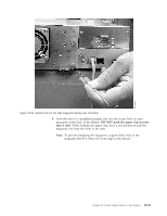
Important: Damage to the connector pins may occur if this procedure is not, followed
 |
View all Dell TL2000 manuals
Add to My Manuals
Save this manual to your list of manuals |
Page 217 highlights
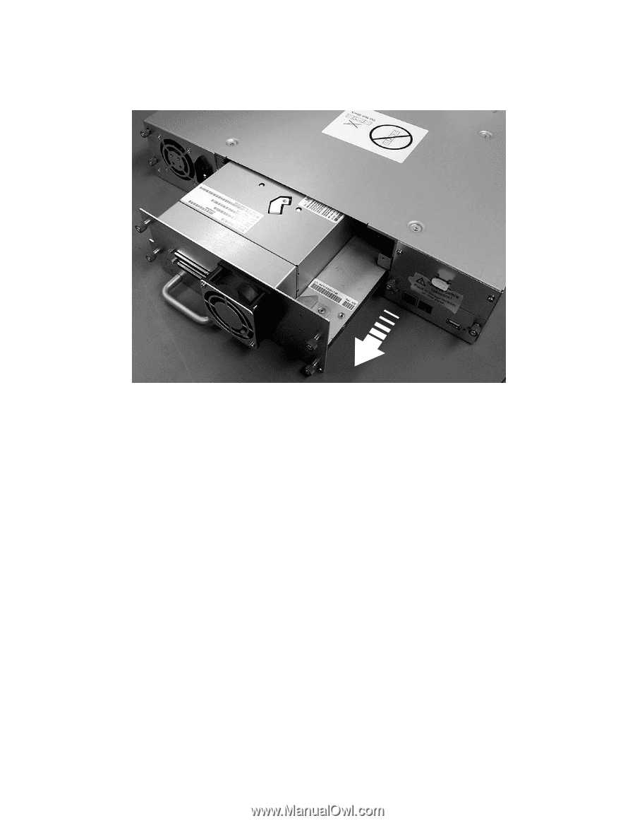
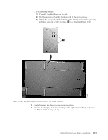
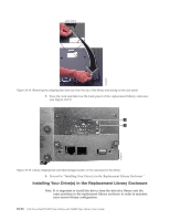
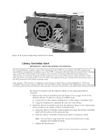
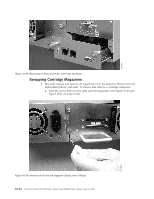
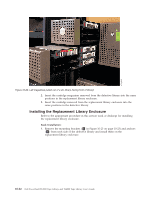
a77ug027 Remove all drives from the defective library (see Figure 10-16) and install them in the same positions in the replacement library enclosure. Figure 10-16. Removing a drive sled from the library (drive sled without ESD springs shown) 1. Ensure the power cord is unplugged from the power source for each Power Supply in the defective library enclosure. 2. On the rear of the defective library, loosen the blue captive thumbscrews on the drive sled. 3. If necessary, remove the conductive tape from the drive sled. 4. Pull back on the tape drive handle to remove it from the library. 5. On the rear of the replacement library enclosure, extend the black pull-out tab located underneath the lower right corner of the lowest drive sled position. Ensure that the black pull-out tab remains extended when inserting a drive sled in the lowest drive position in the library. Important: Damage to the connector pins may occur if this procedure is not followed. 6. Place each tape drive into the replacement library enclosure in the same drive slot as it was positioned in the defective library. v While supporting the drive assembly, align the drive sled with the groove in the drive slot rails. v Slowly push the drive sled forward until it is properly seated. 7. Tighten the captive thumbscrews until the drive is secure. 8. If installing a drive sled without ESD springs (see Figure 10-16), apply conductive tape as shown in Figure 10-17 on page 10-18. Chapter 10. Check, Adjust, Remove, and Replace 10-17
-
 1
1 -
2
-
3
-
4
-
5
-
6
-
7
-
8
-
9
-
10
-
11
-
12
-
13
-
14
-
15
-
16
-
17
-
18
-
19
-
20
-
21
-
22
-
23
-
24
-
25
-
26
-
27
-
28
-
29
-
30
-
31
-
32
-
33
-
34
-
35
-
36
-
37
-
38
-
39
-
40
-
41
-
42
-
43
-
44
-
45
-
46
-
47
-
48
-
49
-
50
-
51
-
52
-
53
-
54
-
55
-
56
-
57
-
58
-
59
-
60
-
61
-
62
-
63
-
64
-
65
-
66
-
67
-
68
-
69
-
70
-
71
-
72
-
73
-
74
-
75
-
76
-
77
-
78
-
79
-
80
-
81
-
82
-
83
-
84
-
85
-
86
-
87
-
88
-
89
-
90
-
91
-
92
-
93
-
94
-
95
-
96
-
97
-
98
-
99
-
100
-
101
-
102
-
103
-
104
-
105
-
106
-
107
-
108
-
109
-
110
-
111
-
112
-
113
-
114
-
115
-
116
-
117
-
118
-
119
-
120
-
121
-
122
-
123
-
124
-
125
-
126
-
127
-
128
-
129
-
130
-
131
-
132
-
133
-
134
-
135
-
136
-
137
-
138
-
139
-
140
-
141
-
142
-
143
-
144
-
145
-
146
-
147
-
148
-
149
-
150
-
151
-
152
-
153
-
154
-
155
-
156
-
157
-
158
-
159
-
160
-
161
-
162
-
163
-
164
-
165
-
166
-
167
-
168
-
169
-
170
-
171
-
172
-
173
-
174
-
175
-
176
-
177
-
178
-
179
-
180
-
181
-
182
-
183
-
184
-
185
-
186
-
187
-
188
-
189
-
190
-
191
-
192
-
193
-
194
-
195
-
196
-
197
-
198
-
199
-
200
-
201
-
202
-
203
-
204
-
205
-
206
-
207
-
208
-
209
-
210
-
211
-
 212
212 -
 213
213 -
 214
214 -
 215
215 -
 216
216 -
 217
217 -
 218
218 -
 219
219 -
 220
220 -
 221
221 -
 222
222 -
223
-
224
-
225
-
226
-
227
-
228
-
229
-
230
-
231
-
232
-
233
-
234
-
235
-
236
-
237
-
238
-
239
-
240
-
241
-
242
-
243
-
244
-
245
-
246
-
247
-
248
-
249
-
250
-
251
-
252
-
253
-
254
-
255
-
256
-
257
-
258
-
259
-
260
-
261
-
262
-
263
-
264
-
265
-
266
-
267
-
268
-
269
-
270
-
271
-
272
-
273
-
274
-
275
-
276
-
277
 |
 |