Dell TL2000 User Guide - Page 27
Number, Description, Flashing, Steady On, For use by Service Personnel. - tape
 |
View all Dell TL2000 manuals
Add to My Manuals
Save this manual to your list of manuals |
Page 27 highlights
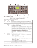
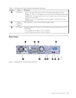
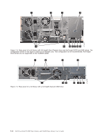
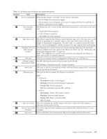
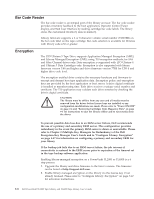
Table 1-2. 2U library and 4U library rear panel descriptions Number 1 2 3 4 5 6 7 8 Item Description Power connector(s) Both libraries require a 110/220 volt AC power connection. v The 2U library has one power supply. v The 4U library has a minimum of one power supply, but has the capability of adding a redundant power supply. Host interface connectors The library has one or more of the following host interface connectors on the drive sled: v a 68-pin HD SCSI connector v a Fibre Channel connector v a SFF-8088 mini-SAS connector Tape drive sled This library supports the Ultrium 3 and Ultrium 4 tape drive. The tape drive in the library is packaged in a container called a drive sled. Drive sleds come in a full height or half height configuration. The drive sled is a customer replaceable unit (CRU), and is hot-pluggable, which is designed for easy removal and replacement. Shipping lock and label storage location The shipping lock, which secures the accessor during shipping, and associated label are stored on the rear panel of the library for future use. See "Removing and Storing the Shipping Lock" on page 4-4. Note: The shipping lock must be removed before powering ON the library to allow the accessor to function properly. USB port Used to save/restore library configuration information on a USB device. Library Control An LED showing the status of the Library Control Board. Board (LCC) LED LED flashing (1 flash per second) - normal operation Serial port This port is used to communicate serially with the library using an RJ-11 connector. For use by Service Personnel. Ethernet port This port is used to connect the library to a network. LED v 10/100 Link - Description: Green: Link Integrity - Flashing: Network synchronization/negotiation - Steady (On): Good connection - Off: No connection between NIC and hub v Activity - Description: Amber: Port traffic indicator - Flashing: Network traffic present - Steady (On): Heavy network traffic - Off: No traffic 9 Tape drive LED This LED indicates the current status of the drive. When the LED is green, it indicates normal drive activity. 10 Service Tag/Serial The service tag and serial number on the pull-out label links the library to your Number warranty. 11 Fan vents These vents allow air to escape from the power supply and tape drive sled. Chapter 1. Product Description 1-5
-
 1
1 -
2
-
3
-
4
-
5
-
6
-
7
-
8
-
9
-
10
-
11
-
12
-
13
-
14
-
15
-
16
-
17
-
18
-
19
-
20
-
21
-
 22
22 -
 23
23 -
 24
24 -
 25
25 -
 26
26 -
 27
27 -
 28
28 -
 29
29 -
 30
30 -
 31
31 -
 32
32 -
33
-
34
-
35
-
36
-
37
-
38
-
39
-
40
-
41
-
42
-
43
-
44
-
45
-
46
-
47
-
48
-
49
-
50
-
51
-
52
-
53
-
54
-
55
-
56
-
57
-
58
-
59
-
60
-
61
-
62
-
63
-
64
-
65
-
66
-
67
-
68
-
69
-
70
-
71
-
72
-
73
-
74
-
75
-
76
-
77
-
78
-
79
-
80
-
81
-
82
-
83
-
84
-
85
-
86
-
87
-
88
-
89
-
90
-
91
-
92
-
93
-
94
-
95
-
96
-
97
-
98
-
99
-
100
-
101
-
102
-
103
-
104
-
105
-
106
-
107
-
108
-
109
-
110
-
111
-
112
-
113
-
114
-
115
-
116
-
117
-
118
-
119
-
120
-
121
-
122
-
123
-
124
-
125
-
126
-
127
-
128
-
129
-
130
-
131
-
132
-
133
-
134
-
135
-
136
-
137
-
138
-
139
-
140
-
141
-
142
-
143
-
144
-
145
-
146
-
147
-
148
-
149
-
150
-
151
-
152
-
153
-
154
-
155
-
156
-
157
-
158
-
159
-
160
-
161
-
162
-
163
-
164
-
165
-
166
-
167
-
168
-
169
-
170
-
171
-
172
-
173
-
174
-
175
-
176
-
177
-
178
-
179
-
180
-
181
-
182
-
183
-
184
-
185
-
186
-
187
-
188
-
189
-
190
-
191
-
192
-
193
-
194
-
195
-
196
-
197
-
198
-
199
-
200
-
201
-
202
-
203
-
204
-
205
-
206
-
207
-
208
-
209
-
210
-
211
-
212
-
213
-
214
-
215
-
216
-
217
-
218
-
219
-
220
-
221
-
222
-
223
-
224
-
225
-
226
-
227
-
228
-
229
-
230
-
231
-
232
-
233
-
234
-
235
-
236
-
237
-
238
-
239
-
240
-
241
-
242
-
243
-
244
-
245
-
246
-
247
-
248
-
249
-
250
-
251
-
252
-
253
-
254
-
255
-
256
-
257
-
258
-
259
-
260
-
261
-
262
-
263
-
264
-
265
-
266
-
267
-
268
-
269
-
270
-
271
-
272
-
273
-
274
-
275
-
276
-
277
 |
 |