Dell TL2000 User Guide - Page 228
Mixing of Drives, Configuration of a 1 - Partition System, Configuration of a 2 - Partition System
 |
View all Dell TL2000 manuals
Add to My Manuals
Save this manual to your list of manuals |
Page 228 highlights
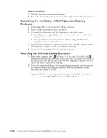
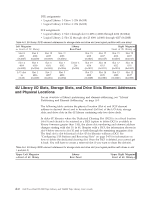
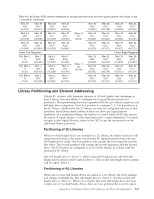
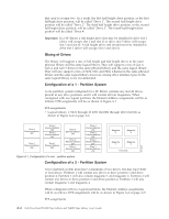
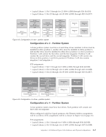
that used to occupy two. As a result, the first half height drive position, or the first full-high drive position, will be called "Drive 1". The second half height drive position will be called "Drive 2". The third half height drive position, or the second full height drive position, will be called "Drive 3". The fourth half height drive position will be called "Drive 4". Important: In a 4U library a full height drive sled may be installed in drive slot 1 (drive will occupy slot 1 and slot 2) or drive slot 3 (drive will occupy slot 3 and slot 4). A full height drive sled should never be installed in drive slot 2 (drive will occupy slot 2 and slot 3). Mixing of Drives The library will support a mix of full height and half height drives in the same physical library and the same logical library. They will support a mix of Gen 3, Gen 4, and Gen 5 drives in the same physical library and the same logical library. They will also support a mix of SCSI, SAS, and Fibre Channel in the same physical library and the same logical library; however, mixing drive interface types in the same logical library is not recommended. Configuration of a 1 - Partition System A one partition system configured for a 4U library contains any and all drives present in any drive positions, and it will contain all four magazines. When configured with one logical partition, the Element Address assignments will be as follows: DTE assignments will be as shown in Figure A-1 STE assignments v Logical Library 1: Slot1 through 23 4096 (0x1000) through 4118 (0x1016) as shown in Figure A-4 on page A-6 Drive 2 Element Address 257 Drive 1 Element Address 256 Drive 4 Element Address 259 Drive 3 Element Address 258 Drive 1 Element Address 256 Drive 3 Element Address 258 Drive 2 Element Address 257 Drive 1 Element Address 256 Drive 4 Element Address 259 Drive 3 Element Address 258 Drive 2 Element Address 257 Drive 1 Element Address 256 Figure A-1. Configuration of a one - partition system Configuration of a 2 - Partition System Magazine 2 Magazine 4 Magazine 1 Magazine 3 Front side a77ug161 A two partition system must have a minimum of two drives, but may have three or four drives. Partition 1 will contain any drives in drive position 1 and drive position 2. Partition 1 will also contain magazine 1 and magazine 2. Partition 2 will contain any drives in drive position 3 and drive position 4. Partition 2 will also contain magazine 3 and magazine 4. When configured with two logical partitions, the Element Address assignments will be as follows: DTE assignments will be as shown in Figure A-2 on page A-5. STE assignments A-4 Dell PowerVault TL2000 Tape Library and TL4000 Tape Library User's Guide
-
 1
1 -
2
-
3
-
4
-
5
-
6
-
7
-
8
-
9
-
10
-
11
-
12
-
13
-
14
-
15
-
16
-
17
-
18
-
19
-
20
-
21
-
22
-
23
-
24
-
25
-
26
-
27
-
28
-
29
-
30
-
31
-
32
-
33
-
34
-
35
-
36
-
37
-
38
-
39
-
40
-
41
-
42
-
43
-
44
-
45
-
46
-
47
-
48
-
49
-
50
-
51
-
52
-
53
-
54
-
55
-
56
-
57
-
58
-
59
-
60
-
61
-
62
-
63
-
64
-
65
-
66
-
67
-
68
-
69
-
70
-
71
-
72
-
73
-
74
-
75
-
76
-
77
-
78
-
79
-
80
-
81
-
82
-
83
-
84
-
85
-
86
-
87
-
88
-
89
-
90
-
91
-
92
-
93
-
94
-
95
-
96
-
97
-
98
-
99
-
100
-
101
-
102
-
103
-
104
-
105
-
106
-
107
-
108
-
109
-
110
-
111
-
112
-
113
-
114
-
115
-
116
-
117
-
118
-
119
-
120
-
121
-
122
-
123
-
124
-
125
-
126
-
127
-
128
-
129
-
130
-
131
-
132
-
133
-
134
-
135
-
136
-
137
-
138
-
139
-
140
-
141
-
142
-
143
-
144
-
145
-
146
-
147
-
148
-
149
-
150
-
151
-
152
-
153
-
154
-
155
-
156
-
157
-
158
-
159
-
160
-
161
-
162
-
163
-
164
-
165
-
166
-
167
-
168
-
169
-
170
-
171
-
172
-
173
-
174
-
175
-
176
-
177
-
178
-
179
-
180
-
181
-
182
-
183
-
184
-
185
-
186
-
187
-
188
-
189
-
190
-
191
-
192
-
193
-
194
-
195
-
196
-
197
-
198
-
199
-
200
-
201
-
202
-
203
-
204
-
205
-
206
-
207
-
208
-
209
-
210
-
211
-
212
-
213
-
214
-
215
-
216
-
217
-
218
-
219
-
220
-
221
-
222
-
 223
223 -
 224
224 -
 225
225 -
 226
226 -
 227
227 -
 228
228 -
 229
229 -
 230
230 -
 231
231 -
 232
232 -
 233
233 -
234
-
235
-
236
-
237
-
238
-
239
-
240
-
241
-
242
-
243
-
244
-
245
-
246
-
247
-
248
-
249
-
250
-
251
-
252
-
253
-
254
-
255
-
256
-
257
-
258
-
259
-
260
-
261
-
262
-
263
-
264
-
265
-
266
-
267
-
268
-
269
-
270
-
271
-
272
-
273
-
274
-
275
-
276
-
277
 |
 |