Epson 3800 Service Manual - Page 105
Operation, Panel, Assy.
 |
UPC - 010343862081
View all Epson 3800 manuals
Add to My Manuals
Save this manual to your list of manuals |
Page 105 highlights
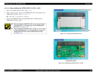
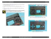
EPSON Stylus Pro 3800/3800C/3850 4.3.3.11 OPERATION, PANEL, ASSY. 1. Remove the HOUSING, REAR, ASSY. (p95) 2. Remove the HOUSING, FRONT, RIGHT. (p98) 3. Remove the HOUSING, RIGHT. (p103) 4. Release the FFC from the OPERATION, PANEL, ASSY. See Figure 4-17. 5. Remove the screw that secures the OPERATION, PANEL, ASSY. to the main unit. See Figure 4-17. „ One C.B.S. 3 x 6 screw (9 ± 1 kgf.cm) 6. Release the hook that secures the OPERATION, PANEL, ASSY. and remove it. See Figure 4-18. Be sure to insert the two ribs on the OPERATION, PANEL, ASSY. into the positioning holes on the main unit. OPERATION, PANEL, ASSY. Connector Revision A FFC C.B.S. 3x6 Figure 4-17. Removing the OPERATION, PANEL, ASSY. (1) DISASSEMBLY & ASSEMBLY hook Figure 4-18. Removing the OPERATION, PANEL, ASSY. (2) Disassembly/Assembly Procedure (Group 1) 105
-
 1
1 -
2
-
3
-
4
-
5
-
6
-
7
-
8
-
9
-
10
-
11
-
12
-
13
-
14
-
15
-
16
-
17
-
18
-
19
-
20
-
21
-
22
-
23
-
24
-
25
-
26
-
27
-
28
-
29
-
30
-
31
-
32
-
33
-
34
-
35
-
36
-
37
-
38
-
39
-
40
-
41
-
42
-
43
-
44
-
45
-
46
-
47
-
48
-
49
-
50
-
51
-
52
-
53
-
54
-
55
-
56
-
57
-
58
-
59
-
60
-
61
-
62
-
63
-
64
-
65
-
66
-
67
-
68
-
69
-
70
-
71
-
72
-
73
-
74
-
75
-
76
-
77
-
78
-
79
-
80
-
81
-
82
-
83
-
84
-
85
-
86
-
87
-
88
-
89
-
90
-
91
-
92
-
93
-
94
-
95
-
96
-
97
-
98
-
99
-
 100
100 -
 101
101 -
 102
102 -
 103
103 -
 104
104 -
 105
105 -
 106
106 -
 107
107 -
 108
108 -
 109
109 -
 110
110 -
111
-
112
-
113
-
114
-
115
-
116
-
117
-
118
-
119
-
120
-
121
-
122
-
123
-
124
-
125
-
126
-
127
-
128
-
129
-
130
-
131
-
132
-
133
-
134
-
135
-
136
-
137
-
138
-
139
-
140
-
141
-
142
-
143
-
144
-
145
-
146
-
147
-
148
-
149
-
150
-
151
-
152
-
153
-
154
-
155
-
156
-
157
-
158
-
159
-
160
-
161
-
162
-
163
-
164
-
165
-
166
-
167
-
168
-
169
-
170
-
171
-
172
-
173
-
174
-
175
-
176
-
177
-
178
-
179
-
180
-
181
-
182
-
183
-
184
-
185
-
186
-
187
-
188
-
189
-
190
-
191
-
192
-
193
-
194
-
195
-
196
-
197
-
198
-
199
-
200
-
201
-
202
-
203
-
204
-
205
-
206
-
207
-
208
-
209
-
210
-
211
-
212
-
213
-
214
-
215
-
216
-
217
-
218
-
219
-
220
-
221
-
222
-
223
-
224
-
225
-
226
-
227
-
228
-
229
-
230
-
231
-
232
-
233
-
234
-
235
-
236
-
237
-
238
-
239
-
240
-
241
-
242
-
243
-
244
-
245
-
246
-
247
-
248
-
249
-
250
-
251
-
252
-
253
-
254
-
255
-
256
-
257
-
258
-
259
-
260
-
261
-
262
-
263
-
264
-
265
-
266
-
267
-
268
-
269
-
270
-
271
-
272
-
273
-
274
-
275
-
276
-
277
-
278
-
279
-
280
-
281
-
282
-
283
-
284
-
285
-
286
 |
 |
