Epson 3800 Service Manual - Page 110
Base, Enclosure
 |
UPC - 010343862081
View all Epson 3800 manuals
Add to My Manuals
Save this manual to your list of manuals |
Page 110 highlights
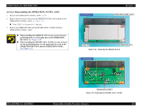
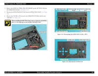
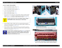
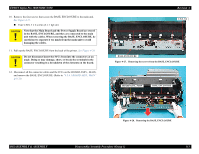
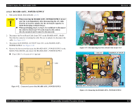
EPSON Stylus Pro 3800/3800C/3850 4.3.3.15 BASE, ENCLOSURE 1. Remove the HOUSING, REAR, ASSY. (p95) 2. Remove the HOUSING, FRONT, LEFT. (p97) 3. Remove the HOUSING, FRONT, RIGHT. (p98) 4. remove the COVER, PRINTER. (p99) 5. Remove the HOUSING, LEFT. (p102) 6. Remove the HOUSING, RIGHT. (p103) 7. Push outward on the circled points of the FRAME, PAPER, SUPPORT, REAR shown in Figure 4-25 to widen it to disengage the four guide pins of the ASF, ASSY, and remove the FRAME, PAPER, SUPPORT, REAR. See Figure 4-25. C A U T IO N In step 8. and 9, do not remove the PAPER, GUIDE, LOWER, LEFT/RIGHT forcibly as their hooks are easily broken. guide pins guide pins Revision A 8. Pull the PAPER, GUIDE, LOWER, LEFT first rearward and then upward to release it from the eight hooks, and pull out the PAPER, GUIDE, LOWER, LEFT from the back of the printer. See Figure 4-26. 9. Pull the PAPER, GUIDE, LOWER, RIGHT first rearward and then upward to release it from the 10 hooks, and pull out the PAPER, GUIDE, LOWER, RIGHT from the back of the printer. See Figure 4-26. CHECK P O IN T The ASF, ASSY. is temporally removed in Figure 4-26 to show the positions of the hooks on the PAPER, GUIDE, LOWER, LEFT/ RIGHT. Note that the ASF, ASSY. is installed on the main unit during the actual maintenance work. FRAME, PAPER, SUPPRT, REAR Figure 4-25. Removing the FRAME, PAPER, SUPPORT, REAR hook ASF, ASSY. DISASSEMBLY & ASSEMBLY PAPER, GUIDE, LOWER, RIGHT PAPER, GUIDE, LOWER, LEFT Figure 4-26. Removing the PAPER, GUIDE, LOWER, LEFT/RIGHT Disassembly/Assembly Procedure (Group 1) 110
-
 1
1 -
2
-
3
-
4
-
5
-
6
-
7
-
8
-
9
-
10
-
11
-
12
-
13
-
14
-
15
-
16
-
17
-
18
-
19
-
20
-
21
-
22
-
23
-
24
-
25
-
26
-
27
-
28
-
29
-
30
-
31
-
32
-
33
-
34
-
35
-
36
-
37
-
38
-
39
-
40
-
41
-
42
-
43
-
44
-
45
-
46
-
47
-
48
-
49
-
50
-
51
-
52
-
53
-
54
-
55
-
56
-
57
-
58
-
59
-
60
-
61
-
62
-
63
-
64
-
65
-
66
-
67
-
68
-
69
-
70
-
71
-
72
-
73
-
74
-
75
-
76
-
77
-
78
-
79
-
80
-
81
-
82
-
83
-
84
-
85
-
86
-
87
-
88
-
89
-
90
-
91
-
92
-
93
-
94
-
95
-
96
-
97
-
98
-
99
-
100
-
101
-
102
-
103
-
104
-
 105
105 -
 106
106 -
 107
107 -
 108
108 -
 109
109 -
 110
110 -
 111
111 -
 112
112 -
 113
113 -
 114
114 -
 115
115 -
116
-
117
-
118
-
119
-
120
-
121
-
122
-
123
-
124
-
125
-
126
-
127
-
128
-
129
-
130
-
131
-
132
-
133
-
134
-
135
-
136
-
137
-
138
-
139
-
140
-
141
-
142
-
143
-
144
-
145
-
146
-
147
-
148
-
149
-
150
-
151
-
152
-
153
-
154
-
155
-
156
-
157
-
158
-
159
-
160
-
161
-
162
-
163
-
164
-
165
-
166
-
167
-
168
-
169
-
170
-
171
-
172
-
173
-
174
-
175
-
176
-
177
-
178
-
179
-
180
-
181
-
182
-
183
-
184
-
185
-
186
-
187
-
188
-
189
-
190
-
191
-
192
-
193
-
194
-
195
-
196
-
197
-
198
-
199
-
200
-
201
-
202
-
203
-
204
-
205
-
206
-
207
-
208
-
209
-
210
-
211
-
212
-
213
-
214
-
215
-
216
-
217
-
218
-
219
-
220
-
221
-
222
-
223
-
224
-
225
-
226
-
227
-
228
-
229
-
230
-
231
-
232
-
233
-
234
-
235
-
236
-
237
-
238
-
239
-
240
-
241
-
242
-
243
-
244
-
245
-
246
-
247
-
248
-
249
-
250
-
251
-
252
-
253
-
254
-
255
-
256
-
257
-
258
-
259
-
260
-
261
-
262
-
263
-
264
-
265
-
266
-
267
-
268
-
269
-
270
-
271
-
272
-
273
-
274
-
275
-
276
-
277
-
278
-
279
-
280
-
281
-
282
-
283
-
284
-
285
-
286
 |
 |
