HP 6125XLG R2306-HP 6125XLG Blade Switch IP Multicast Configuration Guide - Page 170
Enable IPv6 multicast routing, MLD, and IPv6 PIM-DM, Device, Interface, IPv6 address
 |
View all HP 6125XLG manuals
Add to My Manuals
Save this manual to your list of manuals |
Page 170 highlights
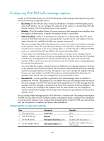
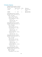
Table 10 Interface and IPv6 address assignment Device Switch A Switch A Switch B Switch B Switch C Switch C Switch D Switch D Switch D Switch D Interface VLAN-interface 100 VLAN-interface 103 VLAN-interface 200 VLAN-interface 101 VLAN-interface 200 VLAN-interface 102 VLAN-interface 300 VLAN-interface 103 VLAN-interface 101 VLAN-interface 102 IPv6 address 1001::1/64 1002::1/64 2001::1/64 2002::1/64 2001::2/64 3001::1/64 4001::1/64 1002::2/64 2002::2/64 3001::2/64 Configuration procedure 1. Assign the IPv6 address and prefix length to each interface according to Figure 53. (Details not shown.) 2. Configure OSPFv3 on the switches in the IPv6 PIM-DM domain to make sure they are interoperable at the network layer and routing information among the switches is dynamically updated. (Details not shown.) 3. Enable IPv6 multicast routing, MLD, and IPv6 PIM-DM: # On Switch A, enable IPv6 multicast routing, enable MLD on VLAN-interface 100, and enable IPv6 PIM-DM on each interface. system-view [SwitchA] ipv6 multicast routing-enable [SwitchA] interface vlan-interface 100 [SwitchA-Vlan-interface100] mld enable [SwitchA-Vlan-interface100] ipv6 pim dm [SwitchA-Vlan-interface100] quit [SwitchA] interface vlan-interface 103 [SwitchA-Vlan-interface103] ipv6 pim dm [SwitchA-Vlan-interface103] quit # Enable IPv6 multicast routing, MLD, and IPv6 PIM-DM on Switch B and Switch C in the same way. (Details not shown.) # On Switch D, enable IPv6 multicast routing, and enable IPv6 PIM-DM on each interface. system-view [SwitchD] ipv6 multicast routing-enable [SwitchD] interface vlan-interface 300 [SwitchD-Vlan-interface300] ipv6 pim dm [SwitchD-Vlan-interface300] quit [SwitchD] interface vlan-interface 103 [SwitchD-Vlan-interface103] ipv6 pim dm [SwitchD-Vlan-interface103] quit [SwitchD] interface vlan-interface 101 163
-
 1
1 -
2
-
3
-
4
-
5
-
6
-
7
-
8
-
9
-
10
-
11
-
12
-
13
-
14
-
15
-
16
-
17
-
18
-
19
-
20
-
21
-
22
-
23
-
24
-
25
-
26
-
27
-
28
-
29
-
30
-
31
-
32
-
33
-
34
-
35
-
36
-
37
-
38
-
39
-
40
-
41
-
42
-
43
-
44
-
45
-
46
-
47
-
48
-
49
-
50
-
51
-
52
-
53
-
54
-
55
-
56
-
57
-
58
-
59
-
60
-
61
-
62
-
63
-
64
-
65
-
66
-
67
-
68
-
69
-
70
-
71
-
72
-
73
-
74
-
75
-
76
-
77
-
78
-
79
-
80
-
81
-
82
-
83
-
84
-
85
-
86
-
87
-
88
-
89
-
90
-
91
-
92
-
93
-
94
-
95
-
96
-
97
-
98
-
99
-
100
-
101
-
102
-
103
-
104
-
105
-
106
-
107
-
108
-
109
-
110
-
111
-
112
-
113
-
114
-
115
-
116
-
117
-
118
-
119
-
120
-
121
-
122
-
123
-
124
-
125
-
126
-
127
-
128
-
129
-
130
-
131
-
132
-
133
-
134
-
135
-
136
-
137
-
138
-
139
-
140
-
141
-
142
-
143
-
144
-
145
-
146
-
147
-
148
-
149
-
150
-
151
-
152
-
153
-
154
-
155
-
156
-
157
-
158
-
159
-
160
-
161
-
162
-
163
-
164
-
 165
165 -
 166
166 -
 167
167 -
 168
168 -
 169
169 -
 170
170 -
 171
171 -
 172
172 -
 173
173 -
 174
174 -
 175
175 -
176
-
177
-
178
-
179
-
180
-
181
-
182
-
183
-
184
-
185
-
186
-
187
-
188
-
189
-
190
-
191
-
192
-
193
-
194
-
195
-
196
-
197
-
198
-
199
-
200
-
201
-
202
-
203
-
204
-
205
-
206
-
207
-
208
-
209
-
210
-
211
 |
 |
