HP 6125XLG R2306-HP 6125XLG Blade Switch IP Multicast Configuration Guide - Page 51
Verifying the configuration, Multicast forwarding over a GRE tunnel, Network requirements
 |
View all HP 6125XLG manuals
Add to My Manuals
Save this manual to your list of manuals |
Page 51 highlights
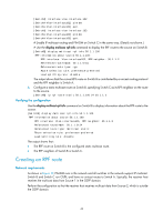
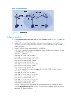
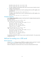
[SwitchB] display multicast rpf-info 50.1.1.100 [SwitchC] display multicast rpf-info 50.1.1.100 No output is displayed. It means that that no RPF routes to Source 2 exist on Switch B or Switch C. 4. Configure a static multicast route: # Configure a static multicast route on Switch B, specifying Switch A as its RPF neighbor on the route to Source 2. [SwitchB] ip rpf-route-static 50.1.1.100 24 30.1.1.2 # Configure a static multicast route on Switch C, specifying Switch B as its RPF neighbor on the route to Source 2. [SwitchC] ip rpf-route-static 10.1.1.100 24 20.1.1.2 Verifying the configuration Use the display multicast rpf-info command on Switch B and Switch C to display information about their RPF routes to Source 2. [SwitchB] display multicast rpf-info 50.1.1.100 RPF information about source 50.1.1.100: RPF interface: Vlan-interface102, RPF neighbor: 30.1.1.2 Referenced route/mask: 50.1.1.0/24 Referenced route type: multicast static Route selection rule: preference-preferred Load splitting rule: disable [SwitchC] display multicast rpf-info 50.1.1.100 RPF information about source 50.1.1.100: RPF interface: Vlan-interface101, RPF neighbor: 20.1.1.2 Referenced route/mask: 50.1.1.0/24 Referenced route type: multicast static Route selection rule: preference-preferred Load splitting rule: disable The output shows that the RPF routes to Source 2 exist on Switch B and Switch C. The routes are the configured static routes. Multicast forwarding over a GRE tunnel Network requirements As shown in Figure 20, Multicast routing and PIM-DM are enabled on Switch A and Switch C. Switch B does not support multicast. OSPF is running on Switch A, Switch B, and Switch C. Perform the configuration so that the receiver host can receive the multicast data from the source. 44
-
 1
1 -
2
-
3
-
4
-
5
-
6
-
7
-
8
-
9
-
10
-
11
-
12
-
13
-
14
-
15
-
16
-
17
-
18
-
19
-
20
-
21
-
22
-
23
-
24
-
25
-
26
-
27
-
28
-
29
-
30
-
31
-
32
-
33
-
34
-
35
-
36
-
37
-
38
-
39
-
40
-
41
-
42
-
43
-
44
-
45
-
 46
46 -
 47
47 -
 48
48 -
 49
49 -
 50
50 -
 51
51 -
 52
52 -
 53
53 -
 54
54 -
 55
55 -
 56
56 -
57
-
58
-
59
-
60
-
61
-
62
-
63
-
64
-
65
-
66
-
67
-
68
-
69
-
70
-
71
-
72
-
73
-
74
-
75
-
76
-
77
-
78
-
79
-
80
-
81
-
82
-
83
-
84
-
85
-
86
-
87
-
88
-
89
-
90
-
91
-
92
-
93
-
94
-
95
-
96
-
97
-
98
-
99
-
100
-
101
-
102
-
103
-
104
-
105
-
106
-
107
-
108
-
109
-
110
-
111
-
112
-
113
-
114
-
115
-
116
-
117
-
118
-
119
-
120
-
121
-
122
-
123
-
124
-
125
-
126
-
127
-
128
-
129
-
130
-
131
-
132
-
133
-
134
-
135
-
136
-
137
-
138
-
139
-
140
-
141
-
142
-
143
-
144
-
145
-
146
-
147
-
148
-
149
-
150
-
151
-
152
-
153
-
154
-
155
-
156
-
157
-
158
-
159
-
160
-
161
-
162
-
163
-
164
-
165
-
166
-
167
-
168
-
169
-
170
-
171
-
172
-
173
-
174
-
175
-
176
-
177
-
178
-
179
-
180
-
181
-
182
-
183
-
184
-
185
-
186
-
187
-
188
-
189
-
190
-
191
-
192
-
193
-
194
-
195
-
196
-
197
-
198
-
199
-
200
-
201
-
202
-
203
-
204
-
205
-
206
-
207
-
208
-
209
-
210
-
211
 |
 |
