HP 6125XLG R2306-HP 6125XLG Blade Switch IP Multicast Configuration Guide - Page 176
IPv6 PIM-SM admin-scoped zone configuration example, Network requirements
 |
View all HP 6125XLG manuals
Add to My Manuals
Save this manual to your list of manuals |
Page 176 highlights
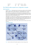
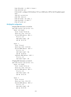
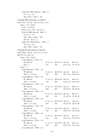
RP address 1003::2 4002::1 Priority 192 192 HoldTime 180 180 Uptime 00:05:19 00:05:19 Expires 00:02:11 00:02:11 IPv6 PIM-SM admin-scoped zone configuration example Network requirements As shown in Figure 55, VOD streams are sent to receiver hosts in multicast. The entire IPv6 PIM-SM domain is divided into IPv6 admin-scoped zone 1, IPv6 admin-scoped zone 2, and the IPv6 global-scoped zone. Switch B, Switch C, and Switch D are ZBRs of the three zones, respectively. Source 1 and Source 2 send different IPv6 multicast data to the IPv6 multicast group FF14::101. Host A receives the IPv6 multicast data only from Source 1, and Host B receives the IPv6 multicast data only from Source 2. Source 3 sends IPv6 multicast data to the IPv6 multicast group FF1E::202. Host C is an IPv6 multicast receiver for the IPv6 multicast group FF1E::202. VLAN-interface 101 of Switch B acts as a C-BSR and a C-RP for IPv6 admin-scoped zone 1, and VLAN-interface 105 of Switch D acts as a C-BSR and a C-RP for IPv6 admin-scoped zone 2. Both of the two interfaces provide services for the IPv6 multicast groups with the scope field value of 4. VLAN-interface 109 of Switch F acts as a C-BSR and a C-RP for the IPv6 global-scoped zone, and it provides services for the IPv6 multicast groups with the scope field value of 14. MLDv1 runs between Switch A, Switch E, Switch I, and the receivers that directly connect to them, respectively. Figure 55 Network diagram Vlan-int600 Vlan-int103 Vlan-int103 Vlan-int300 Vlan-int104 Vlan-int104 Table 12 shows the interface and IPv6 address assignment, and network topology scheme. 169
-
 1
1 -
2
-
3
-
4
-
5
-
6
-
7
-
8
-
9
-
10
-
11
-
12
-
13
-
14
-
15
-
16
-
17
-
18
-
19
-
20
-
21
-
22
-
23
-
24
-
25
-
26
-
27
-
28
-
29
-
30
-
31
-
32
-
33
-
34
-
35
-
36
-
37
-
38
-
39
-
40
-
41
-
42
-
43
-
44
-
45
-
46
-
47
-
48
-
49
-
50
-
51
-
52
-
53
-
54
-
55
-
56
-
57
-
58
-
59
-
60
-
61
-
62
-
63
-
64
-
65
-
66
-
67
-
68
-
69
-
70
-
71
-
72
-
73
-
74
-
75
-
76
-
77
-
78
-
79
-
80
-
81
-
82
-
83
-
84
-
85
-
86
-
87
-
88
-
89
-
90
-
91
-
92
-
93
-
94
-
95
-
96
-
97
-
98
-
99
-
100
-
101
-
102
-
103
-
104
-
105
-
106
-
107
-
108
-
109
-
110
-
111
-
112
-
113
-
114
-
115
-
116
-
117
-
118
-
119
-
120
-
121
-
122
-
123
-
124
-
125
-
126
-
127
-
128
-
129
-
130
-
131
-
132
-
133
-
134
-
135
-
136
-
137
-
138
-
139
-
140
-
141
-
142
-
143
-
144
-
145
-
146
-
147
-
148
-
149
-
150
-
151
-
152
-
153
-
154
-
155
-
156
-
157
-
158
-
159
-
160
-
161
-
162
-
163
-
164
-
165
-
166
-
167
-
168
-
169
-
170
-
 171
171 -
 172
172 -
 173
173 -
 174
174 -
 175
175 -
 176
176 -
 177
177 -
 178
178 -
 179
179 -
 180
180 -
 181
181 -
182
-
183
-
184
-
185
-
186
-
187
-
188
-
189
-
190
-
191
-
192
-
193
-
194
-
195
-
196
-
197
-
198
-
199
-
200
-
201
-
202
-
203
-
204
-
205
-
206
-
207
-
208
-
209
-
210
-
211
 |
 |
