HP 6125XLG R2306-HP 6125XLG Blade Switch IP Multicast Configuration Guide - Page 99
Enable IP multicast routing and PIM-SM on Switch C, Switch D, and Switch, On Switch B
 |
View all HP 6125XLG manuals
Add to My Manuals
Save this manual to your list of manuals |
Page 99 highlights
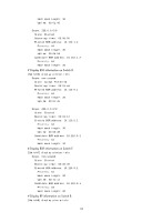
Configuration procedure 1. Assign an IP address and subnet mask to each interface according to Figure 34. (Details not shown.) 2. Enable OSPF on all switches on the PIM-SM network to make sure the network-layer on the PIM-SM network is interoperable and the routing information among the switches can be dynamically updated. (Details not shown.) 3. Enable IP multicast routing, and enable IGMP and PIM-SM: # On Switch A, enable IP multicast routing globally, enable IGMP on VLAN-interface 100, and enable PIM-SM on each interface. system-view [SwitchA] multicast routing-enable [SwitchA] interface vlan-interface 100 [SwitchA-Vlan-interface100] igmp enable [SwitchA-Vlan-interface100] pim sm [SwitchA-Vlan-interface100] quit [SwitchA] interface vlan-interface 101 [SwitchA-Vlan-interface101] pim sm [SwitchA-Vlan-interface101] quit # Enable IP multicast routing, IGMP, and PIM-SM on Switch E and Switch I in the same way. (Details not shown.) # On Switch B, enable IP multicast routing globally, and enable PIM-SM on each interface. system-view [SwitchB] multicast routing-enable [SwitchB] interface vlan-interface 200 [SwitchB-Vlan-interface200] pim sm [SwitchB-Vlan-interface200] quit [SwitchB] interface vlan-interface 101 [SwitchB-Vlan-interface101] pim sm [SwitchB-Vlan-interface101] quit [SwitchB] interface vlan-interface 102 [SwitchB-Vlan-interface102] pim sm [SwitchB-Vlan-interface102] quit [SwitchB] interface vlan-interface 103 [SwitchB-Vlan-interface103] pim sm [SwitchB-Vlan-interface103] quit # Enable IP multicast routing and PIM-SM on Switch C, Switch D, Switch F, Switch G, and Switch H in the same way. (Details not shown.) 4. Configure admin-scoped zone boundaries: # On Switch B, configure VLAN-interface 102 and VLAN-interface 103 as the boundaries of admin-scoped zone 1. [SwitchB] interface vlan-interface 102 [SwitchB-Vlan-interface102] multicast boundary 239.0.0.0 8 [SwitchB-Vlan-interface102] quit [SwitchB] interface vlan-interface 103 [SwitchB-Vlan-interface103] multicast boundary 239.0.0.0 8 [SwitchB-Vlan-interface103] quit 92
-
 1
1 -
2
-
3
-
4
-
5
-
6
-
7
-
8
-
9
-
10
-
11
-
12
-
13
-
14
-
15
-
16
-
17
-
18
-
19
-
20
-
21
-
22
-
23
-
24
-
25
-
26
-
27
-
28
-
29
-
30
-
31
-
32
-
33
-
34
-
35
-
36
-
37
-
38
-
39
-
40
-
41
-
42
-
43
-
44
-
45
-
46
-
47
-
48
-
49
-
50
-
51
-
52
-
53
-
54
-
55
-
56
-
57
-
58
-
59
-
60
-
61
-
62
-
63
-
64
-
65
-
66
-
67
-
68
-
69
-
70
-
71
-
72
-
73
-
74
-
75
-
76
-
77
-
78
-
79
-
80
-
81
-
82
-
83
-
84
-
85
-
86
-
87
-
88
-
89
-
90
-
91
-
92
-
93
-
 94
94 -
 95
95 -
 96
96 -
 97
97 -
 98
98 -
 99
99 -
 100
100 -
 101
101 -
 102
102 -
 103
103 -
 104
104 -
105
-
106
-
107
-
108
-
109
-
110
-
111
-
112
-
113
-
114
-
115
-
116
-
117
-
118
-
119
-
120
-
121
-
122
-
123
-
124
-
125
-
126
-
127
-
128
-
129
-
130
-
131
-
132
-
133
-
134
-
135
-
136
-
137
-
138
-
139
-
140
-
141
-
142
-
143
-
144
-
145
-
146
-
147
-
148
-
149
-
150
-
151
-
152
-
153
-
154
-
155
-
156
-
157
-
158
-
159
-
160
-
161
-
162
-
163
-
164
-
165
-
166
-
167
-
168
-
169
-
170
-
171
-
172
-
173
-
174
-
175
-
176
-
177
-
178
-
179
-
180
-
181
-
182
-
183
-
184
-
185
-
186
-
187
-
188
-
189
-
190
-
191
-
192
-
193
-
194
-
195
-
196
-
197
-
198
-
199
-
200
-
201
-
202
-
203
-
204
-
205
-
206
-
207
-
208
-
209
-
210
-
211
 |
 |
