HP 6125XLG R2306-HP 6125XLG Blade Switch IP Multicast Configuration Guide - Page 52
Configuration procedure
 |
View all HP 6125XLG manuals
Add to My Manuals
Save this manual to your list of manuals |
Page 52 highlights
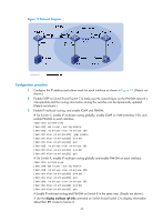
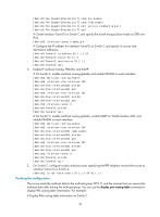
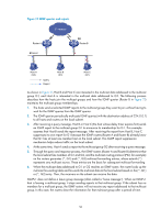
Figure 20 Network diagram Configuration procedure 1. Configure the IP address and subnet mask for each interface as shown in Figure 20. (Details not shown.) 2. Enable OSPF on switches to make sure the network-layer among the switches is interoperable and the routing information among the switches can be dynamically updated. (Details not shown.) 3. Configure a GRE tunnel: # Create service loopback group 1 on Switch A and specify its service type as Tunnel. system-view [SwitchA] service-loopback group 1 type tunnel # Disable STP and NDP on interface Ten-GigabitEthernet 1/1/7 of Switch A, and add the interface to service loopback group 1. Ten-GigabitEthernet 1/1/7 does not belong to VLAN 100 or VLAN 101. [SwitchA] interface ten-gigabitethernet 1/1/7 [SwitchA-Ten-GigabitEthernet1/1/7] undo stp enable [SwitchA-Ten-GigabitEthernet1/1/7] undo lldp enable [SwitchA-Ten-GigabitEthernet1/1/7] port service-loopback group 1 [SwitchA-Ten-GigabitEthernet1/1/7] quit # Create interface Tunnel 0 on Switch A and specify the tunnel encapsulation mode as GRE over IPv4. [SwitchA] interface tunnel 0 mode gre # Configure the IP address for interface Tunnel 0 on Switch A and specify its source and destination addresses. [SwitchA-Tunnel0] ip address 50.1.1.1 24 [SwitchA-Tunnel0] source 20.1.1.1 [SwitchA-Tunnel0] destination 30.1.1.2 [SwitchA-Tunnel0] quit # Create service loopback group 1 on Switch C and specify its service type as Tunnel. system-view [SwitchC] service-loopback group 1 type tunnel # Disable STP and NDP on interface Ten-GigabitEthernet 1/1/7 of Switch C, and add the interface to service loopback group 1. Ten-GigabitEthernet 1/1/7 does not belong to VLAN 200 or VLAN 102. [SwitchC] interface ten-gigabitethernet 1/1/7 45
-
 1
1 -
2
-
3
-
4
-
5
-
6
-
7
-
8
-
9
-
10
-
11
-
12
-
13
-
14
-
15
-
16
-
17
-
18
-
19
-
20
-
21
-
22
-
23
-
24
-
25
-
26
-
27
-
28
-
29
-
30
-
31
-
32
-
33
-
34
-
35
-
36
-
37
-
38
-
39
-
40
-
41
-
42
-
43
-
44
-
45
-
46
-
 47
47 -
 48
48 -
 49
49 -
 50
50 -
 51
51 -
 52
52 -
 53
53 -
 54
54 -
 55
55 -
 56
56 -
 57
57 -
58
-
59
-
60
-
61
-
62
-
63
-
64
-
65
-
66
-
67
-
68
-
69
-
70
-
71
-
72
-
73
-
74
-
75
-
76
-
77
-
78
-
79
-
80
-
81
-
82
-
83
-
84
-
85
-
86
-
87
-
88
-
89
-
90
-
91
-
92
-
93
-
94
-
95
-
96
-
97
-
98
-
99
-
100
-
101
-
102
-
103
-
104
-
105
-
106
-
107
-
108
-
109
-
110
-
111
-
112
-
113
-
114
-
115
-
116
-
117
-
118
-
119
-
120
-
121
-
122
-
123
-
124
-
125
-
126
-
127
-
128
-
129
-
130
-
131
-
132
-
133
-
134
-
135
-
136
-
137
-
138
-
139
-
140
-
141
-
142
-
143
-
144
-
145
-
146
-
147
-
148
-
149
-
150
-
151
-
152
-
153
-
154
-
155
-
156
-
157
-
158
-
159
-
160
-
161
-
162
-
163
-
164
-
165
-
166
-
167
-
168
-
169
-
170
-
171
-
172
-
173
-
174
-
175
-
176
-
177
-
178
-
179
-
180
-
181
-
182
-
183
-
184
-
185
-
186
-
187
-
188
-
189
-
190
-
191
-
192
-
193
-
194
-
195
-
196
-
197
-
198
-
199
-
200
-
201
-
202
-
203
-
204
-
205
-
206
-
207
-
208
-
209
-
210
-
211
 |
 |
