HP 6125XLG R2306-HP 6125XLG Blade Switch IP Multicast Configuration Guide - Page 33
IGMP snooping configuration examples, Group policy configuration example, Network requirements
 |
View all HP 6125XLG manuals
Add to My Manuals
Save this manual to your list of manuals |
Page 33 highlights
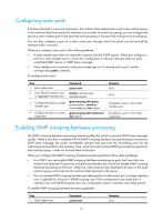
Task Display information about MAC address multicast forwarding entries. Remove the dynamic IGMP snooping forwarding entries for the specified multicast groups. Remove dynamic router ports. Clear statistics for the IGMP messages learned by IGMP snooping. Command display l2-multicast mac-forwarding-table [ mac-address ] [ vlan vlan-id ] [ slot slot-number ] reset igmp-snooping group { group-address [ source-address ] | all } [ vlan vlan-id ] reset igmp-snooping router-port { all | vlan vlan-id } reset igmp-snooping statistics IGMP snooping configuration examples Group policy configuration example Network requirements As shown in Figure 12, Router A runs IGMPv2 and serves as the IGMP querier, and Switch A runs IGMPv2 snooping. To enable Host A and Host B to receive only the multicast data addressed to the multicast group 224.1.1.1, configure IGMP snooping on Switch A and enable the switch to drop unknown multicast data instead of flooding it in VLAN 100. Figure 12 Network diagram Receiver Host A Source XGE1/1/6 1.1.1.2/24 XGE1/1/5 10.1.1.1/24 XGE1/1/5 XGE1/1/8 XGE1/1/7 Receiver 1.1.1.1/24 Router A IGMP querier Switch A XGE1/1/6 Host B Host C VLAN 100 Configuration procedure 1. Assign an IP address and subnet mask to each interface according to Figure 12. (Details not shown.) 2. On Router A, enable IP multicast routing globally, enable IGMP on Ten-GigabitEthernet 1/1/5, and enable PIM-DM on each interface. system-view 26
-
 1
1 -
2
-
3
-
4
-
5
-
6
-
7
-
8
-
9
-
10
-
11
-
12
-
13
-
14
-
15
-
16
-
17
-
18
-
19
-
20
-
21
-
22
-
23
-
24
-
25
-
26
-
27
-
 28
28 -
 29
29 -
 30
30 -
 31
31 -
 32
32 -
 33
33 -
 34
34 -
 35
35 -
 36
36 -
 37
37 -
 38
38 -
39
-
40
-
41
-
42
-
43
-
44
-
45
-
46
-
47
-
48
-
49
-
50
-
51
-
52
-
53
-
54
-
55
-
56
-
57
-
58
-
59
-
60
-
61
-
62
-
63
-
64
-
65
-
66
-
67
-
68
-
69
-
70
-
71
-
72
-
73
-
74
-
75
-
76
-
77
-
78
-
79
-
80
-
81
-
82
-
83
-
84
-
85
-
86
-
87
-
88
-
89
-
90
-
91
-
92
-
93
-
94
-
95
-
96
-
97
-
98
-
99
-
100
-
101
-
102
-
103
-
104
-
105
-
106
-
107
-
108
-
109
-
110
-
111
-
112
-
113
-
114
-
115
-
116
-
117
-
118
-
119
-
120
-
121
-
122
-
123
-
124
-
125
-
126
-
127
-
128
-
129
-
130
-
131
-
132
-
133
-
134
-
135
-
136
-
137
-
138
-
139
-
140
-
141
-
142
-
143
-
144
-
145
-
146
-
147
-
148
-
149
-
150
-
151
-
152
-
153
-
154
-
155
-
156
-
157
-
158
-
159
-
160
-
161
-
162
-
163
-
164
-
165
-
166
-
167
-
168
-
169
-
170
-
171
-
172
-
173
-
174
-
175
-
176
-
177
-
178
-
179
-
180
-
181
-
182
-
183
-
184
-
185
-
186
-
187
-
188
-
189
-
190
-
191
-
192
-
193
-
194
-
195
-
196
-
197
-
198
-
199
-
200
-
201
-
202
-
203
-
204
-
205
-
206
-
207
-
208
-
209
-
210
-
211
 |
 |
