HP 6125XLG R2306-HP 6125XLG Blade Switch IP Multicast Configuration Guide - Page 64
Network diagram, Enable IP multicast routing, and enable IGMP and PIM-DM
 |
View all HP 6125XLG manuals
Add to My Manuals
Save this manual to your list of manuals |
Page 64 highlights
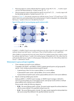
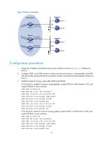
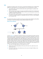
Figure 23 Network diagram PIM network Vlan-int101 Vlan-int100 Switch A 10.110.1.1/24 Querier Vlan-int201 Vlan-int200 10.110.2.1/24 Switch B Vlan-int202 Vlan-int200 10.110.2.2/24 Switch C Receiver Host A N1 Host B Receiver Host C N2 Host D Configuration procedure 1. Assign the IP address and subnet mask to each interface as shown in Figure 23. (Details not shown.) 2. Configure OSPF on the PIM network to make sure the network-layer is interoperable on the PIM network and the routing information among the switches can be dynamically updated. (Details not shown.) 3. Enable IP multicast routing, and enable IGMP and PIM-DM: # On Switch A, enable IP multicast routing globally, enable IGMP on VLAN-interface 100, and enable PIM-DM on each interface. system-view [SwitchA] multicast routing-enable [SwitchA] interface vlan-interface 100 [SwitchA-Vlan-interface100] igmp enable [SwitchA-Vlan-interface100] pim dm [SwitchA-Vlan-interface100] quit [SwitchA] interface vlan-interface 101 [SwitchA-Vlan-interface101] pim dm [SwitchA-Vlan-interface101] quit # On Switch B, enable IP multicast routing globally, enable IGMP on VLAN-interface 200, and enable PIM-DM on each interface. system-view [SwitchB] multicast routing-enable [SwitchB] interface vlan-interface 200 [SwitchB-Vlan-interface200] igmp enable [SwitchB-Vlan-interface200] pim dm [SwitchB-Vlan-interface200] quit 57
-
 1
1 -
2
-
3
-
4
-
5
-
6
-
7
-
8
-
9
-
10
-
11
-
12
-
13
-
14
-
15
-
16
-
17
-
18
-
19
-
20
-
21
-
22
-
23
-
24
-
25
-
26
-
27
-
28
-
29
-
30
-
31
-
32
-
33
-
34
-
35
-
36
-
37
-
38
-
39
-
40
-
41
-
42
-
43
-
44
-
45
-
46
-
47
-
48
-
49
-
50
-
51
-
52
-
53
-
54
-
55
-
56
-
57
-
58
-
 59
59 -
 60
60 -
 61
61 -
 62
62 -
 63
63 -
 64
64 -
 65
65 -
 66
66 -
 67
67 -
 68
68 -
 69
69 -
70
-
71
-
72
-
73
-
74
-
75
-
76
-
77
-
78
-
79
-
80
-
81
-
82
-
83
-
84
-
85
-
86
-
87
-
88
-
89
-
90
-
91
-
92
-
93
-
94
-
95
-
96
-
97
-
98
-
99
-
100
-
101
-
102
-
103
-
104
-
105
-
106
-
107
-
108
-
109
-
110
-
111
-
112
-
113
-
114
-
115
-
116
-
117
-
118
-
119
-
120
-
121
-
122
-
123
-
124
-
125
-
126
-
127
-
128
-
129
-
130
-
131
-
132
-
133
-
134
-
135
-
136
-
137
-
138
-
139
-
140
-
141
-
142
-
143
-
144
-
145
-
146
-
147
-
148
-
149
-
150
-
151
-
152
-
153
-
154
-
155
-
156
-
157
-
158
-
159
-
160
-
161
-
162
-
163
-
164
-
165
-
166
-
167
-
168
-
169
-
170
-
171
-
172
-
173
-
174
-
175
-
176
-
177
-
178
-
179
-
180
-
181
-
182
-
183
-
184
-
185
-
186
-
187
-
188
-
189
-
190
-
191
-
192
-
193
-
194
-
195
-
196
-
197
-
198
-
199
-
200
-
201
-
202
-
203
-
204
-
205
-
206
-
207
-
208
-
209
-
210
-
211
 |
 |
