HP 6125XLG R2306-HP 6125XLG Blade Switch IP Multicast Configuration Guide - Page 172
IPv6 PIM-SM non-scoped zone configuration example, Network requirements
 |
View all HP 6125XLG manuals
Add to My Manuals
Save this manual to your list of manuals |
Page 172 highlights
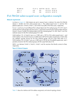
Protocol: pim-dm, Flag: ACT UpTime: 00:01:20 Upstream interface: Vlan-interface103 Upstream neighbor: 1002::2 RPF prime neighbor: 1002::2 Downstream interface(s) information: Total number of downstreams: 1 1: Vlan-interface100 Protocol: pim-dm, UpTime: 00:01:20, Expires: - # Display IPv6 PIM multicast routing table information on Switch D. [SwitchD] display ipv6 pim routing-table Total 0 (*, G) entry; 1 (S, G) entry (4001::100, FF0E::101) Protocol: pim-dm, Flag: LOC ACT UpTime: 00:02:19 Upstream interface: Vlan-interface300 Upstream neighbor: NULL RPF prime neighbor: NULL Downstream interface(s) information: Total number of downstreams: 2 1: Vlan-interface103 Protocol: pim-dm, UpTime: 00:02:19, Expires: 2: Vlan-interface102 Protocol: pim-dm, UpTime: 00:02:19, Expires: - IPv6 PIM-SM non-scoped zone configuration example Network requirements As shown in Figure 54, VOD streams are sent to receiver hosts in multicast. The receivers of different subnets form stub networks, and at least one receiver host exist in each stub network. The entire IPv6 PIM-SM domain contains only one BSR. Host A and Host C are multicast receivers in the stub networks N1 and N2. VLAN-interface 105 on Switch D and VLAN-interface 102 on Switch E act as C-BSRs and C-RPs. The C-BSR on Switch E has a higher priority. The C-RPs provide services for the IPv6 multicast group range FF0E::101/64. Modify the hash mask length to map the IPv6 multicast group range to the two C-RPs. MLDv1 runs between Switch A and N1, and between Switch B, Switch C, and N2. 165
-
 1
1 -
2
-
3
-
4
-
5
-
6
-
7
-
8
-
9
-
10
-
11
-
12
-
13
-
14
-
15
-
16
-
17
-
18
-
19
-
20
-
21
-
22
-
23
-
24
-
25
-
26
-
27
-
28
-
29
-
30
-
31
-
32
-
33
-
34
-
35
-
36
-
37
-
38
-
39
-
40
-
41
-
42
-
43
-
44
-
45
-
46
-
47
-
48
-
49
-
50
-
51
-
52
-
53
-
54
-
55
-
56
-
57
-
58
-
59
-
60
-
61
-
62
-
63
-
64
-
65
-
66
-
67
-
68
-
69
-
70
-
71
-
72
-
73
-
74
-
75
-
76
-
77
-
78
-
79
-
80
-
81
-
82
-
83
-
84
-
85
-
86
-
87
-
88
-
89
-
90
-
91
-
92
-
93
-
94
-
95
-
96
-
97
-
98
-
99
-
100
-
101
-
102
-
103
-
104
-
105
-
106
-
107
-
108
-
109
-
110
-
111
-
112
-
113
-
114
-
115
-
116
-
117
-
118
-
119
-
120
-
121
-
122
-
123
-
124
-
125
-
126
-
127
-
128
-
129
-
130
-
131
-
132
-
133
-
134
-
135
-
136
-
137
-
138
-
139
-
140
-
141
-
142
-
143
-
144
-
145
-
146
-
147
-
148
-
149
-
150
-
151
-
152
-
153
-
154
-
155
-
156
-
157
-
158
-
159
-
160
-
161
-
162
-
163
-
164
-
165
-
166
-
 167
167 -
 168
168 -
 169
169 -
 170
170 -
 171
171 -
 172
172 -
 173
173 -
 174
174 -
 175
175 -
 176
176 -
 177
177 -
178
-
179
-
180
-
181
-
182
-
183
-
184
-
185
-
186
-
187
-
188
-
189
-
190
-
191
-
192
-
193
-
194
-
195
-
196
-
197
-
198
-
199
-
200
-
201
-
202
-
203
-
204
-
205
-
206
-
207
-
208
-
209
-
210
-
211
 |
 |
