HP 6930p HP EliteBook 6930p Notebook PC - Maintenance and Service Guide - Page 104
Phillips PM2.5×4.0 screw, securing the system board to the base enclosure.
 |
UPC - 884962659670
View all HP 6930p manuals
Add to My Manuals
Save this manual to your list of manuals |
Page 104 highlights
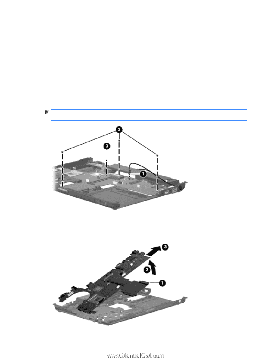
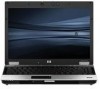
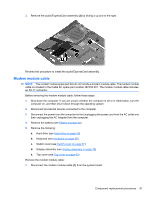
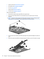
● WLAN module (see WLAN module on page 63) ● RTC battery (see RTC battery on page 66) ● Fan (see Fan on page 70) ● Heat sink (see Heat sink on page 71) ● Processor (see Processor on page 76) Remove the system board: 1. Disconnect the modem module cable (1) from the system board. 2. Remove the three Phillips PM2.5×4.0 screws (2) that secure the system board to the base enclosure. NOTE: Computer models equipped with UMA graphics subsystem memory will have a fourth Phillips PM2.5×4.0 screw (3) securing the system board to the base enclosure. 3. Use the optical drive connector (1) to lift the right edge of the system board (2) until it rests at an angle. 4. Remove the system board (3) from the base enclosure by sliding it up and to the right at an angle. 94 Chapter 4 Removal and replacement procedures
-
 1
1 -
2
-
3
-
4
-
5
-
6
-
7
-
8
-
9
-
10
-
11
-
12
-
13
-
14
-
15
-
16
-
17
-
18
-
19
-
20
-
21
-
22
-
23
-
24
-
25
-
26
-
27
-
28
-
29
-
30
-
31
-
32
-
33
-
34
-
35
-
36
-
37
-
38
-
39
-
40
-
41
-
42
-
43
-
44
-
45
-
46
-
47
-
48
-
49
-
50
-
51
-
52
-
53
-
54
-
55
-
56
-
57
-
58
-
59
-
60
-
61
-
62
-
63
-
64
-
65
-
66
-
67
-
68
-
69
-
70
-
71
-
72
-
73
-
74
-
75
-
76
-
77
-
78
-
79
-
80
-
81
-
82
-
83
-
84
-
85
-
86
-
87
-
88
-
89
-
90
-
91
-
92
-
93
-
94
-
95
-
96
-
97
-
98
-
 99
99 -
 100
100 -
 101
101 -
 102
102 -
 103
103 -
 104
104 -
 105
105 -
 106
106 -
 107
107 -
 108
108 -
 109
109 -
110
-
111
-
112
-
113
-
114
-
115
-
116
-
117
-
118
-
119
-
120
-
121
-
122
-
123
-
124
-
125
-
126
-
127
-
128
-
129
-
130
-
131
-
132
-
133
-
134
-
135
-
136
-
137
-
138
-
139
-
140
-
141
-
142
-
143
-
144
-
145
-
146
-
147
-
148
-
149
-
150
-
151
-
152
-
153
-
154
-
155
-
156
-
157
-
158
-
159
-
160
-
161
-
162
-
163
-
164
-
165
-
166
-
167
-
168
-
169
-
170
-
171
-
172
 |
 |