HP 6930p HP EliteBook 6930p Notebook PC - Maintenance and Service Guide - Page 27
Bottom components
 |
UPC - 884962659670
View all HP 6930p manuals
Add to My Manuals
Save this manual to your list of manuals |
Page 27 highlights
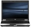
Bottom components Item (1) (2) (3) Component Battery bay Docking connector Vents (5) (4) Accessory battery connector (5) Memory module compartment (6) Hard drive bay (7) WWAN module compartment (8) Battery release latch (9) SIM slot (select models only) Function Holds the battery. Connects an optional docking device. Enable airflow to cool internal components. CAUTION: To prevent overheating, do not obstruct vents. Use the computer only on a hard, flat surface. Do not allow another hard surface, such as an adjoining optional printer, or a soft surface, such as pillows or thick rugs or clothing, to block airflow. NOTE: The computer fan starts up automatically to cool internal components and prevent overheating. It is normal for the internal fan to cycle on and off during routine operation. Connects an optional accessory battery. Contains the expansion memory module slot. Holds the hard drive. Contains a WWAN module (select models only). CAUTION: To prevent an unresponsive system and the display of a warning message, replace the device with only a WLAN module authorized for use in the computer by the governmental agency that regulates wireless devices in your country. If you replace the device and then receive a warning message, remove the device to restore computer functionality, and then contact technical support through Help and Support. Releases the battery from the battery bay. Contains a wireless subscriber identity module (SIM). The SIM slot is located inside the battery bay. Bottom components 17
-
 1
1 -
2
-
3
-
4
-
5
-
6
-
7
-
8
-
9
-
10
-
11
-
12
-
13
-
14
-
15
-
16
-
17
-
18
-
19
-
20
-
21
-
 22
22 -
 23
23 -
 24
24 -
 25
25 -
 26
26 -
 27
27 -
 28
28 -
 29
29 -
 30
30 -
 31
31 -
 32
32 -
33
-
34
-
35
-
36
-
37
-
38
-
39
-
40
-
41
-
42
-
43
-
44
-
45
-
46
-
47
-
48
-
49
-
50
-
51
-
52
-
53
-
54
-
55
-
56
-
57
-
58
-
59
-
60
-
61
-
62
-
63
-
64
-
65
-
66
-
67
-
68
-
69
-
70
-
71
-
72
-
73
-
74
-
75
-
76
-
77
-
78
-
79
-
80
-
81
-
82
-
83
-
84
-
85
-
86
-
87
-
88
-
89
-
90
-
91
-
92
-
93
-
94
-
95
-
96
-
97
-
98
-
99
-
100
-
101
-
102
-
103
-
104
-
105
-
106
-
107
-
108
-
109
-
110
-
111
-
112
-
113
-
114
-
115
-
116
-
117
-
118
-
119
-
120
-
121
-
122
-
123
-
124
-
125
-
126
-
127
-
128
-
129
-
130
-
131
-
132
-
133
-
134
-
135
-
136
-
137
-
138
-
139
-
140
-
141
-
142
-
143
-
144
-
145
-
146
-
147
-
148
-
149
-
150
-
151
-
152
-
153
-
154
-
155
-
156
-
157
-
158
-
159
-
160
-
161
-
162
-
163
-
164
-
165
-
166
-
167
-
168
-
169
-
170
-
171
-
172
 |
 |
