HP 6930p HP EliteBook 6930p Notebook PC - Maintenance and Service Guide - Page 83
with all heat sink, system board, and processor spare part kits.
 |
UPC - 884962659670
View all HP 6930p manuals
Add to My Manuals
Save this manual to your list of manuals |
Page 83 highlights
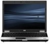
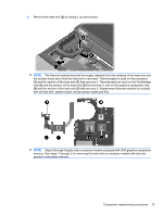
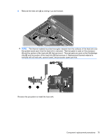
5. Remove the heat sink (3) by sliding it up and forward. NOTE: The thermal material must be thoroughly cleaned from the surfaces of the heat sink and the system board each time the heat sink is removed. Thermal paste is used on the processor (1) and the section of the heat sink (1) that services it. Thermal pads are used on the Northbridge chip (2) and the section of the heat sink (2) that services it, and on the graphics subsystem chip (3) and the section of the heat sink (3) that services it. Replacement thermal material is included with all heat sink, system board, and processor spare part kits. NOTE: Steps 6 through 8 apply only to computer models equipped with UMA graphics subsystem memory. See steps 1 through 5 for removing the heat sink on computer models with discrete graphics subsystem memory. Component replacement procedures 73
-
 1
1 -
2
-
3
-
4
-
5
-
6
-
7
-
8
-
9
-
10
-
11
-
12
-
13
-
14
-
15
-
16
-
17
-
18
-
19
-
20
-
21
-
22
-
23
-
24
-
25
-
26
-
27
-
28
-
29
-
30
-
31
-
32
-
33
-
34
-
35
-
36
-
37
-
38
-
39
-
40
-
41
-
42
-
43
-
44
-
45
-
46
-
47
-
48
-
49
-
50
-
51
-
52
-
53
-
54
-
55
-
56
-
57
-
58
-
59
-
60
-
61
-
62
-
63
-
64
-
65
-
66
-
67
-
68
-
69
-
70
-
71
-
72
-
73
-
74
-
75
-
76
-
77
-
 78
78 -
 79
79 -
 80
80 -
 81
81 -
 82
82 -
 83
83 -
 84
84 -
 85
85 -
 86
86 -
 87
87 -
 88
88 -
89
-
90
-
91
-
92
-
93
-
94
-
95
-
96
-
97
-
98
-
99
-
100
-
101
-
102
-
103
-
104
-
105
-
106
-
107
-
108
-
109
-
110
-
111
-
112
-
113
-
114
-
115
-
116
-
117
-
118
-
119
-
120
-
121
-
122
-
123
-
124
-
125
-
126
-
127
-
128
-
129
-
130
-
131
-
132
-
133
-
134
-
135
-
136
-
137
-
138
-
139
-
140
-
141
-
142
-
143
-
144
-
145
-
146
-
147
-
148
-
149
-
150
-
151
-
152
-
153
-
154
-
155
-
156
-
157
-
158
-
159
-
160
-
161
-
162
-
163
-
164
-
165
-
166
-
167
-
168
-
169
-
170
-
171
-
172
 |
 |
