HP 6930p HP EliteBook 6930p Notebook PC - Maintenance and Service Guide - Page 94
Seven Torx8 T8M2.5×7.0 screws., One Phillips PM2.0×5.0 screw.
 |
UPC - 884962659670
View all HP 6930p manuals
Add to My Manuals
Save this manual to your list of manuals |
Page 94 highlights
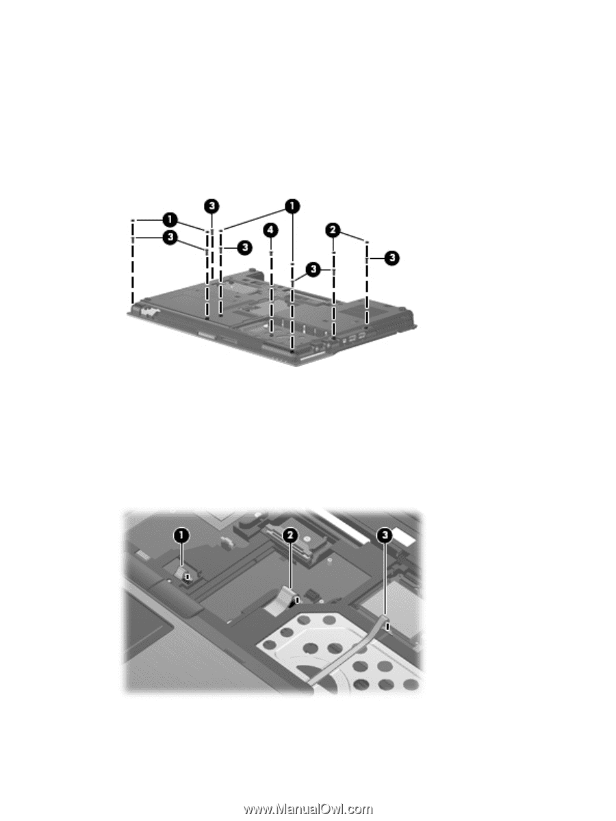
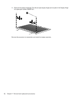
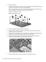
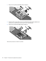
2. Remove the following: (1) Two round rubber screw covers on the front edge of the base enclosure. Rubber screw covers are available in the Rubber Kit, spare part number 482968-001. (2) Two cup-shaped rubber screw covers on the right edge of the base enclosure. Rubber screw covers are available in the Rubber Kit, spare part number 482968-001. (3) Seven Torx8 T8M2.5×7.0 screws. (4) One Phillips PM2.0×5.0 screw. 3. Turn the computer right-side up, with the front toward you. 4. Release the ZIF connector (1) to which the TouchPad cable is attached, and disconnect the TouchPad cable from the system board. 5. Release the ZIF connector (2) to which the audio/ExpressCard assembly cable is attached, and disconnect the audio/ExpressCard assembly cable from the system board. 6. Release the ZIF connector (3) to which the fingerprint reader board cable is attached, and disconnect the fingerprint reader board cable from the system board. 7. Lift the rear edge of the top cover (1) until it detaches from the base enclosure. 84 Chapter 4 Removal and replacement procedures
-
 1
1 -
2
-
3
-
4
-
5
-
6
-
7
-
8
-
9
-
10
-
11
-
12
-
13
-
14
-
15
-
16
-
17
-
18
-
19
-
20
-
21
-
22
-
23
-
24
-
25
-
26
-
27
-
28
-
29
-
30
-
31
-
32
-
33
-
34
-
35
-
36
-
37
-
38
-
39
-
40
-
41
-
42
-
43
-
44
-
45
-
46
-
47
-
48
-
49
-
50
-
51
-
52
-
53
-
54
-
55
-
56
-
57
-
58
-
59
-
60
-
61
-
62
-
63
-
64
-
65
-
66
-
67
-
68
-
69
-
70
-
71
-
72
-
73
-
74
-
75
-
76
-
77
-
78
-
79
-
80
-
81
-
82
-
83
-
84
-
85
-
86
-
87
-
88
-
 89
89 -
 90
90 -
 91
91 -
 92
92 -
 93
93 -
 94
94 -
 95
95 -
 96
96 -
 97
97 -
 98
98 -
 99
99 -
100
-
101
-
102
-
103
-
104
-
105
-
106
-
107
-
108
-
109
-
110
-
111
-
112
-
113
-
114
-
115
-
116
-
117
-
118
-
119
-
120
-
121
-
122
-
123
-
124
-
125
-
126
-
127
-
128
-
129
-
130
-
131
-
132
-
133
-
134
-
135
-
136
-
137
-
138
-
139
-
140
-
141
-
142
-
143
-
144
-
145
-
146
-
147
-
148
-
149
-
150
-
151
-
152
-
153
-
154
-
155
-
156
-
157
-
158
-
159
-
160
-
161
-
162
-
163
-
164
-
165
-
166
-
167
-
168
-
169
-
170
-
171
-
172
 |
 |