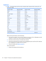
HP 6930p HP EliteBook 6930p Notebook PC - Maintenance and Service Guide - Page 67
by pulling the module away from the slot at an angle., Remove the WWAN module
 |
UPC - 884962659670
View all HP 6930p manuals
Add to My Manuals
Save this manual to your list of manuals |
Page 67 highlights
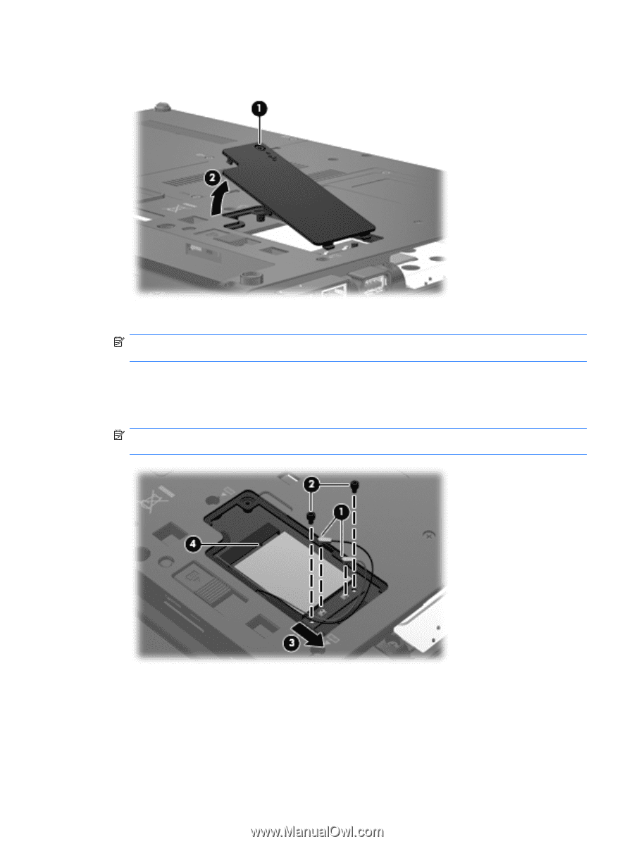
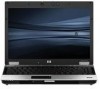
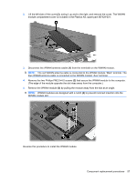
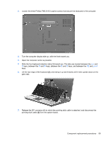
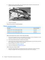
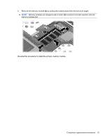
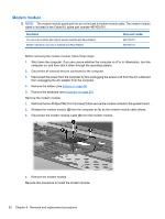
2. Lift the left side of the cover (2), swing it up and to the right, and remove the cover. The WWAN module compartment cover is included in the Plastics Kit, spare part 487429-001. 3. Disconnect the WWAN antenna cables (1) from the terminals on the WWAN module. NOTE: The red WWAN antenna cable is connected to the WWAN module "Main" terminal. The blue WWAN antenna cable is connected to the WWAN module "Aux" terminal. 4. Remove the two Phillips PM2.5×4.0 screws (2) that secure the WWAN module to the computer. (The edge of the module opposite the slot rises away from the computer.) 5. Remove the WWAN module (3) by pulling the module away from the slot at an angle. NOTE: WWAN modules are designed with a notch (4) to prevent incorrect insertion into the WWAN module slot. Reverse this procedure to install the WWAN module. Component replacement procedures 57
-
 1
1 -
2
-
3
-
4
-
5
-
6
-
7
-
8
-
9
-
10
-
11
-
12
-
13
-
14
-
15
-
16
-
17
-
18
-
19
-
20
-
21
-
22
-
23
-
24
-
25
-
26
-
27
-
28
-
29
-
30
-
31
-
32
-
33
-
34
-
35
-
36
-
37
-
38
-
39
-
40
-
41
-
42
-
43
-
44
-
45
-
46
-
47
-
48
-
49
-
50
-
51
-
52
-
53
-
54
-
55
-
56
-
57
-
58
-
59
-
60
-
61
-
 62
62 -
 63
63 -
 64
64 -
 65
65 -
 66
66 -
 67
67 -
 68
68 -
 69
69 -
 70
70 -
 71
71 -
 72
72 -
73
-
74
-
75
-
76
-
77
-
78
-
79
-
80
-
81
-
82
-
83
-
84
-
85
-
86
-
87
-
88
-
89
-
90
-
91
-
92
-
93
-
94
-
95
-
96
-
97
-
98
-
99
-
100
-
101
-
102
-
103
-
104
-
105
-
106
-
107
-
108
-
109
-
110
-
111
-
112
-
113
-
114
-
115
-
116
-
117
-
118
-
119
-
120
-
121
-
122
-
123
-
124
-
125
-
126
-
127
-
128
-
129
-
130
-
131
-
132
-
133
-
134
-
135
-
136
-
137
-
138
-
139
-
140
-
141
-
142
-
143
-
144
-
145
-
146
-
147
-
148
-
149
-
150
-
151
-
152
-
153
-
154
-
155
-
156
-
157
-
158
-
159
-
160
-
161
-
162
-
163
-
164
-
165
-
166
-
167
-
168
-
169
-
170
-
171
-
172
 |
 |