HP 6930p HP EliteBook 6930p Notebook PC - Maintenance and Service Guide - Page 78
board cable from the system board., to which the LED board cable is attached, and disconnect the LED
 |
UPC - 884962659670
View all HP 6930p manuals
Add to My Manuals
Save this manual to your list of manuals |
Page 78 highlights
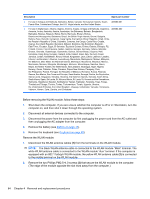
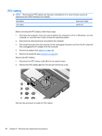
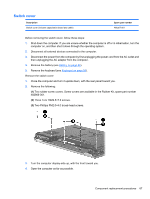
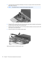
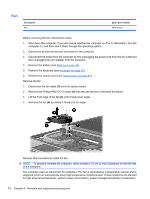
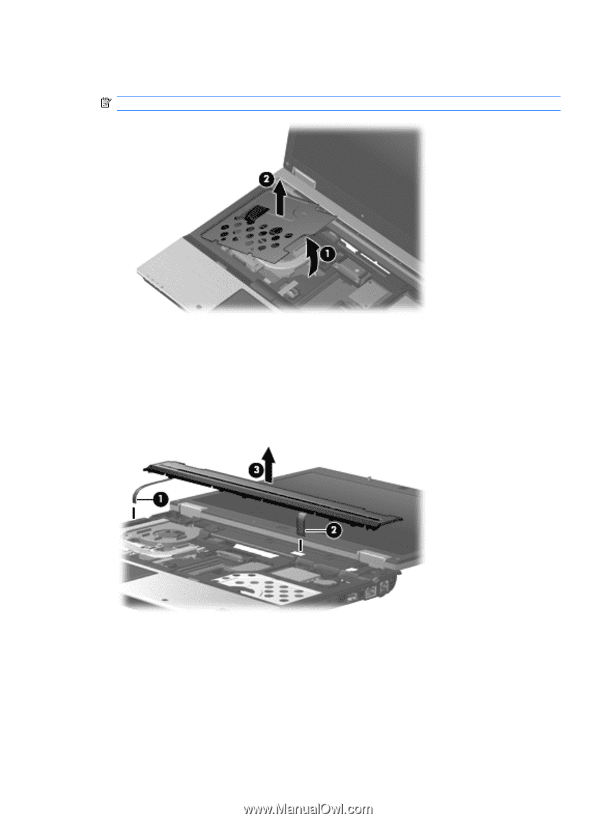
5. Lift the right side of the keyboard shield (1) until it rests at an angle, and then remove the shield (2) by lifting it straight up. NOTE: The keyboard shield is included with the keyboard spare part kit. 6. Release the ZIF connector (1) to which the power button board cable is attached, and disconnect the power button board cable from the system board. 7. Release the ZIF connector (2) to which the LED board cable is attached, and disconnect the LED board cable from the system board. 8. Remove the switch cover by lifting it straight up (3). Reverse this procedure to install the switch cover. 68 Chapter 4 Removal and replacement procedures
-
 1
1 -
2
-
3
-
4
-
5
-
6
-
7
-
8
-
9
-
10
-
11
-
12
-
13
-
14
-
15
-
16
-
17
-
18
-
19
-
20
-
21
-
22
-
23
-
24
-
25
-
26
-
27
-
28
-
29
-
30
-
31
-
32
-
33
-
34
-
35
-
36
-
37
-
38
-
39
-
40
-
41
-
42
-
43
-
44
-
45
-
46
-
47
-
48
-
49
-
50
-
51
-
52
-
53
-
54
-
55
-
56
-
57
-
58
-
59
-
60
-
61
-
62
-
63
-
64
-
65
-
66
-
67
-
68
-
69
-
70
-
71
-
72
-
 73
73 -
 74
74 -
 75
75 -
 76
76 -
 77
77 -
 78
78 -
 79
79 -
 80
80 -
 81
81 -
 82
82 -
 83
83 -
84
-
85
-
86
-
87
-
88
-
89
-
90
-
91
-
92
-
93
-
94
-
95
-
96
-
97
-
98
-
99
-
100
-
101
-
102
-
103
-
104
-
105
-
106
-
107
-
108
-
109
-
110
-
111
-
112
-
113
-
114
-
115
-
116
-
117
-
118
-
119
-
120
-
121
-
122
-
123
-
124
-
125
-
126
-
127
-
128
-
129
-
130
-
131
-
132
-
133
-
134
-
135
-
136
-
137
-
138
-
139
-
140
-
141
-
142
-
143
-
144
-
145
-
146
-
147
-
148
-
149
-
150
-
151
-
152
-
153
-
154
-
155
-
156
-
157
-
158
-
159
-
160
-
161
-
162
-
163
-
164
-
165
-
166
-
167
-
168
-
169
-
170
-
171
-
172
 |
 |
5.
Lift the right side of the keyboard shield
(1)
until it rests at an angle, and then remove the shield
(2)
by lifting it straight up.
NOTE:
The keyboard shield is included with the keyboard spare part kit.
6.
Release the ZIF connector
(1)
to which the power button board cable is attached, and disconnect
the power button board cable from the system board.
7.
Release the ZIF connector
(2)
to which the LED board cable is attached, and disconnect the LED
board cable from the system board.
8.
Remove the switch cover by lifting it straight up
(3)
.
Reverse this procedure to install the switch cover.
68
Chapter 4
Removal and replacement procedures