HP GbE2c HP GbE2c Ethernet Blade Switch for c-Class BladeSystem Browser-based - Page 148
Common Internal Spanning Tree Port Configuration
 |
UPC - 808736802215
View all HP GbE2c manuals
Add to My Manuals
Save this manual to your list of manuals |
Page 148 highlights
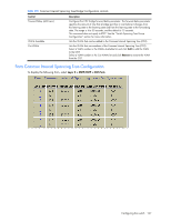
Common Internal Spanning Tree Port Configuration To display the following form, go to the Ports Common Internal Spanning Tree Configuration form. Select a CIST Port number. This form summarizes the port CIST parameters. Common Internal Spanning Tree port parameters are used to modify MSTP operation on an individual port basis. For each port, MSTP is turned on by default. The following table describes the Common Internal Spanning Tree Port Configuration controls: Table 116 Common Internal Spanning Tree Port Configuration controls Control Port Priority (0-240) Path Cost (1-200000000) Link Type Enable/Disable Edge Port STP State Hello Time (1-10 secs) Description Configures the CIST port priority. The port priority helps determine which bridge port becomes the designated port. In a network topology that has multiple bridge ports connected to a single segment, the port with the lowest port priority becomes the designated port for the segment. The range is 0 to 240, in steps of 16 (0, 16, 32...) and the default is 128. Configures the CIST port path cost. The port path cost is used to help determine the designated port for a segment. Generally speaking, the faster the port, the lower the path cost. The default is 20000 for Gigabit ports. Defines the type of link connected to the port, as follows: • auto: Configures the port to detect the link type, and automatically match its settings. • p2p: Configures the port for Point-To-Point protocol. • shared: Configures the port to connect to a shared medium (usually a hub). The default link type is auto. Enables or disables this port as an edge port. An edge port is not connected to a bridge, and can begin forwarding traffic as soon as the link is up. Configure server ports as edge ports (enabled). This command is disabled by default. Turns MSTP on or off for this port. Configures how often "keep alive" BPDU messages are transmitted. Configuring the switch 148
-
 1
1 -
2
-
3
-
4
-
5
-
6
-
7
-
8
-
9
-
10
-
11
-
12
-
13
-
14
-
15
-
16
-
17
-
18
-
19
-
20
-
21
-
22
-
23
-
24
-
25
-
26
-
27
-
28
-
29
-
30
-
31
-
32
-
33
-
34
-
35
-
36
-
37
-
38
-
39
-
40
-
41
-
42
-
43
-
44
-
45
-
46
-
47
-
48
-
49
-
50
-
51
-
52
-
53
-
54
-
55
-
56
-
57
-
58
-
59
-
60
-
61
-
62
-
63
-
64
-
65
-
66
-
67
-
68
-
69
-
70
-
71
-
72
-
73
-
74
-
75
-
76
-
77
-
78
-
79
-
80
-
81
-
82
-
83
-
84
-
85
-
86
-
87
-
88
-
89
-
90
-
91
-
92
-
93
-
94
-
95
-
96
-
97
-
98
-
99
-
100
-
101
-
102
-
103
-
104
-
105
-
106
-
107
-
108
-
109
-
110
-
111
-
112
-
113
-
114
-
115
-
116
-
117
-
118
-
119
-
120
-
121
-
122
-
123
-
124
-
125
-
126
-
127
-
128
-
129
-
130
-
131
-
132
-
133
-
134
-
135
-
136
-
137
-
138
-
139
-
140
-
141
-
142
-
 143
143 -
 144
144 -
 145
145 -
 146
146 -
 147
147 -
 148
148 -
 149
149 -
 150
150 -
 151
151 -
 152
152 -
 153
153 -
154
-
155
-
156
-
157
-
158
-
159
-
160
-
161
-
162
-
163
-
164
-
165
-
166
-
167
-
168
-
169
-
170
-
171
-
172
-
173
-
174
-
175
-
176
-
177
-
178
-
179
-
180
-
181
-
182
-
183
-
184
-
185
-
186
-
187
-
188
-
189
-
190
-
191
-
192
-
193
-
194
-
195
-
196
-
197
-
198
-
199
-
200
-
201
-
202
-
203
-
204
-
205
-
206
-
207
-
208
-
209
 |
 |
