HP GbE2c HP GbE2c Ethernet Blade Switch for c-Class BladeSystem Browser-based - Page 195
VRRP General Configuration, Layer 3 > Virtual Router Redundancy Protocol > General.
 |
UPC - 808736802215
View all HP GbE2c manuals
Add to My Manuals
Save this manual to your list of manuals |
Page 195 highlights
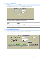
VRRP General Configuration NOTE: This form is available only on the GbE2c Layer 2/3 Ethernet Blade Switch. To display the following form, select Layer 3 > Virtual Router Redundancy Protocol > General. The following table describes the VRRP General Configuration controls: Table 163 VRRP General Configuration controls Control Descriptions VRRP Processing Enabled? VRRP virtual router tracking increment (0-254) VRRP IP interface tracking increment (0-254) VRRP VLAN switch port tracking increment (0-254) Virtual Router Identifier (1-255) IP interface (1-255) Enabled? Priority (1-254) Advertisement Interval (1-255) Globally enables or disables VRRP processing. Defines the priority increment value (1 through 254) for virtual routers in master mode detected on this switch. The default value is 2. Defines the priority increment value (1 through 254) for active IP interfaces detected on this switch. The default value is 2. Defines the priority increment value (1 through 254) for active ports on the virtual router's VLAN. The default value is 2. VRRP Virtual Router Group Configuration Assigns a numeric identifier to the virtual router group. Defines the IP interface associated with the virtual router group. Enables or disables the virtual router group. Defines the election priority bias for this virtual router group. This can be any integer between 1 and 254. The default value is 100. During the master router election process, the routing device with the highest virtual router priority number wins. If there is a tie, the device with the highest IP interface address wins. If this virtual router's IP address (addr) is the same as the one used by the IP interface, the priority for this virtual router will automatically be set to 255 (highest). When priority tracking is used (/cfg/l3/vrrp/track or /cfg/l3/vrrp/vr #/track), this base priority value can be modified according to a number of performance and operational criteria. Defines the time interval between VRRP master advertisements. This can be any integer between 1 and 255 seconds. The default is 1. Configuring the switch 195
-
 1
1 -
2
-
3
-
4
-
5
-
6
-
7
-
8
-
9
-
10
-
11
-
12
-
13
-
14
-
15
-
16
-
17
-
18
-
19
-
20
-
21
-
22
-
23
-
24
-
25
-
26
-
27
-
28
-
29
-
30
-
31
-
32
-
33
-
34
-
35
-
36
-
37
-
38
-
39
-
40
-
41
-
42
-
43
-
44
-
45
-
46
-
47
-
48
-
49
-
50
-
51
-
52
-
53
-
54
-
55
-
56
-
57
-
58
-
59
-
60
-
61
-
62
-
63
-
64
-
65
-
66
-
67
-
68
-
69
-
70
-
71
-
72
-
73
-
74
-
75
-
76
-
77
-
78
-
79
-
80
-
81
-
82
-
83
-
84
-
85
-
86
-
87
-
88
-
89
-
90
-
91
-
92
-
93
-
94
-
95
-
96
-
97
-
98
-
99
-
100
-
101
-
102
-
103
-
104
-
105
-
106
-
107
-
108
-
109
-
110
-
111
-
112
-
113
-
114
-
115
-
116
-
117
-
118
-
119
-
120
-
121
-
122
-
123
-
124
-
125
-
126
-
127
-
128
-
129
-
130
-
131
-
132
-
133
-
134
-
135
-
136
-
137
-
138
-
139
-
140
-
141
-
142
-
143
-
144
-
145
-
146
-
147
-
148
-
149
-
150
-
151
-
152
-
153
-
154
-
155
-
156
-
157
-
158
-
159
-
160
-
161
-
162
-
163
-
164
-
165
-
166
-
167
-
168
-
169
-
170
-
171
-
172
-
173
-
174
-
175
-
176
-
177
-
178
-
179
-
180
-
181
-
182
-
183
-
184
-
185
-
186
-
187
-
188
-
189
-
 190
190 -
 191
191 -
 192
192 -
 193
193 -
 194
194 -
 195
195 -
 196
196 -
 197
197 -
 198
198 -
 199
199 -
 200
200 -
201
-
202
-
203
-
204
-
205
-
206
-
207
-
208
-
209
 |
 |
