HP GbE2c HP GbE2c Ethernet Blade Switch for c-Class BladeSystem Browser-based - Page 182
OSPF Interface Configuration
 |
UPC - 808736802215
View all HP GbE2c manuals
Add to My Manuals
Save this manual to your list of manuals |
Page 182 highlights
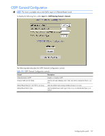
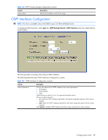
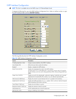
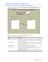
OSPF Interface Configuration NOTE: This form is available only on the GbE2c Layer 2/3 Ethernet Blade Switch. To display the following form, go to the OSPF Interfaces Configuration form. Select an interface number, or open the OSPF Interfaces folder and click Add OSPF Interface. The following table describes the OSPF Interface Configuration controls: Table 150 OSPF Interface Configuration controls Control Descriptions IP Interface Identifier (1-256) Area Number (0-2) Enabled? Router Priority (0-255) Output Cost (1-65535) Hello Interval (1-65535 sec) Dead Interval (1-65535 sec) Transit Delay (1-3600 sec) Retransmit Interval (1-3600 sec) Authentication Key MD5 Key ID (1-255) Assigns a numeric identifier to the OSPF IP interface. Defines the area index used by the interface. Enables or disables the OSPF interface. Displays the assigned priority value to the OSPF interfaces. (A priority value of 127 is the highest and 1 is the lowest. A priority value of 0 specifies that the interface cannot be used as Designated Router (DR) or Backup Designated Router (BDR).) Displays cost set for the selected path-preferred or backup. Usually the cost is inversely proportional to the bandwidth of the interface. Low cost indicates high bandwidth. Displays the interval in seconds between the hello packets for the interfaces. Displays the health parameters of a hello packet, which is set for an interval of seconds before declaring a silent router to be down. Displays the transit delay in seconds. Displays the retransmit interval in seconds. Sets the authentication key to clear the password. Assigns an MD5 key to the interface. Configuring the switch 182
-
 1
1 -
2
-
3
-
4
-
5
-
6
-
7
-
8
-
9
-
10
-
11
-
12
-
13
-
14
-
15
-
16
-
17
-
18
-
19
-
20
-
21
-
22
-
23
-
24
-
25
-
26
-
27
-
28
-
29
-
30
-
31
-
32
-
33
-
34
-
35
-
36
-
37
-
38
-
39
-
40
-
41
-
42
-
43
-
44
-
45
-
46
-
47
-
48
-
49
-
50
-
51
-
52
-
53
-
54
-
55
-
56
-
57
-
58
-
59
-
60
-
61
-
62
-
63
-
64
-
65
-
66
-
67
-
68
-
69
-
70
-
71
-
72
-
73
-
74
-
75
-
76
-
77
-
78
-
79
-
80
-
81
-
82
-
83
-
84
-
85
-
86
-
87
-
88
-
89
-
90
-
91
-
92
-
93
-
94
-
95
-
96
-
97
-
98
-
99
-
100
-
101
-
102
-
103
-
104
-
105
-
106
-
107
-
108
-
109
-
110
-
111
-
112
-
113
-
114
-
115
-
116
-
117
-
118
-
119
-
120
-
121
-
122
-
123
-
124
-
125
-
126
-
127
-
128
-
129
-
130
-
131
-
132
-
133
-
134
-
135
-
136
-
137
-
138
-
139
-
140
-
141
-
142
-
143
-
144
-
145
-
146
-
147
-
148
-
149
-
150
-
151
-
152
-
153
-
154
-
155
-
156
-
157
-
158
-
159
-
160
-
161
-
162
-
163
-
164
-
165
-
166
-
167
-
168
-
169
-
170
-
171
-
172
-
173
-
174
-
175
-
176
-
 177
177 -
 178
178 -
 179
179 -
 180
180 -
 181
181 -
 182
182 -
 183
183 -
 184
184 -
 185
185 -
 186
186 -
 187
187 -
188
-
189
-
190
-
191
-
192
-
193
-
194
-
195
-
196
-
197
-
198
-
199
-
200
-
201
-
202
-
203
-
204
-
205
-
206
-
207
-
208
-
209
 |
 |
