HP GbE2c HP GbE2c Ethernet Blade Switch for c-Class BladeSystem Browser-based - Page 207
Uplink Failure Detection Configuration - team
 |
UPC - 808736802215
View all HP GbE2c manuals
Add to My Manuals
Save this manual to your list of manuals |
Page 207 highlights
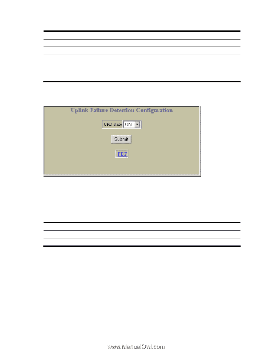
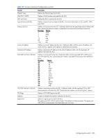
The following table describes the Access Control List Group configuration controls: Table 174 ACL Group Configuration controls Control Description Group ID (1-762) ACLs Available ACLs in Group Assigns a numeric identifier to the ACL Group. Lists the ACLs that you can add to the ACL Group. Lists the ACLs that belong to the ACL Group. Select an ACL number in the ACLs Available list, and click Add to add the ACL to the ACL Group. Select an ACL number in the ACLs in Group list, and click Remove to remove the ACL from the ACL Group. Uplink Failure Detection Configuration To display the following form, select Uplink Failure Detection (click the underlined text, not the folder). Uplink Failure Detection (UFD) supports network fault tolerance in network adapter teams. Use this menu to configure a Failure Detection Pair of one Links to Monitor (LtM) group and one Links to Disable (LtD) group. When UFD is enabled and a Failover Pair is configured, the switch automatically disables ports in the LtD if it detects a failure in the LtM. The failure conditions which are monitored in the LtM group include port link state moving to down, or port state moving to Blocking if Spanning Tree Protocol is enabled. The following table describes the Uplink Failure Detection (UFD) configuration controls: Table 175 Uplink Failure Detection Configuration controls Control Description UFD state FDP Globally turns UFD on or off. Displays the Failure Detection Pair Configuration form. Configuring the switch 207
-
 1
1 -
2
-
3
-
4
-
5
-
6
-
7
-
8
-
9
-
10
-
11
-
12
-
13
-
14
-
15
-
16
-
17
-
18
-
19
-
20
-
21
-
22
-
23
-
24
-
25
-
26
-
27
-
28
-
29
-
30
-
31
-
32
-
33
-
34
-
35
-
36
-
37
-
38
-
39
-
40
-
41
-
42
-
43
-
44
-
45
-
46
-
47
-
48
-
49
-
50
-
51
-
52
-
53
-
54
-
55
-
56
-
57
-
58
-
59
-
60
-
61
-
62
-
63
-
64
-
65
-
66
-
67
-
68
-
69
-
70
-
71
-
72
-
73
-
74
-
75
-
76
-
77
-
78
-
79
-
80
-
81
-
82
-
83
-
84
-
85
-
86
-
87
-
88
-
89
-
90
-
91
-
92
-
93
-
94
-
95
-
96
-
97
-
98
-
99
-
100
-
101
-
102
-
103
-
104
-
105
-
106
-
107
-
108
-
109
-
110
-
111
-
112
-
113
-
114
-
115
-
116
-
117
-
118
-
119
-
120
-
121
-
122
-
123
-
124
-
125
-
126
-
127
-
128
-
129
-
130
-
131
-
132
-
133
-
134
-
135
-
136
-
137
-
138
-
139
-
140
-
141
-
142
-
143
-
144
-
145
-
146
-
147
-
148
-
149
-
150
-
151
-
152
-
153
-
154
-
155
-
156
-
157
-
158
-
159
-
160
-
161
-
162
-
163
-
164
-
165
-
166
-
167
-
168
-
169
-
170
-
171
-
172
-
173
-
174
-
175
-
176
-
177
-
178
-
179
-
180
-
181
-
182
-
183
-
184
-
185
-
186
-
187
-
188
-
189
-
190
-
191
-
192
-
193
-
194
-
195
-
196
-
197
-
198
-
199
-
200
-
201
-
 202
202 -
 203
203 -
 204
204 -
 205
205 -
 206
206 -
 207
207 -
 208
208 -
 209
209
 |
 |