HP Pavilion 900 HP Pavilion Desktop PCs - DVDRW - (English) Technical Support - Page 18
Tray Locking Mechanism
 |
View all HP Pavilion 900 manuals
Add to My Manuals
Save this manual to your list of manuals |
Page 18 highlights
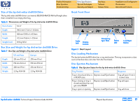
Product Information Drive Operation Troubleshooting Drive Specifications Tips and Techniques Warranty and Support Interfaces Software Release Notes Installation and Configuration Maintenance Discontinued Products Manual Ejection The drive has a manual ejection button on the front bezel. When pressed, it activates the electrical signal to open and close the tray. The manual ejection facility functions upon power-up, but it can be disabled by the host computer through the Prevent/ Allow Medium Removal command. Emergency Ejection The tray is ejectable by pushing a pin or standard size paper clip into the emergency eject pinhole on the front bezel (see Figure 3). The emergency ejection mechanism functions even without power to the drive and with the prevent bit set. Table 9 Emergency Ejection Specification Maximum force 3.5 Kgf Stroke of pin insertion 40 mm Recommended diameter of pin 1.2 mm Auto Insertion The tray automatically closes when it is pushed. Table 10 Auto Insertion Specification Maximum force 5.5 Kgf Stroke 3 mm The drive is designed to respond within 1 second. Ejecting Position The tray is ejected approximately 64.5 mm from the front of the front bezel to the center of the disc. Tray Locking Mechanism There is a locking mechanism on the tray such that when power is off and the tray is closed, the tray will be locked in a closed position. This locking mechanism has a manual override. LEDs The drive has one LED visible on the front bezel. The use of the LED is described in Table 11 LED Protocol. Table 11 LED Protocol Drive State LED No disc inserted OFF Disc is loading or being ejected Disc in, drive in standby mode Solid Orange Disc not readable Blinks Orange Decoder Fail Blinks Orange EEPROM Fail Blinks Orange DRAM Fail Blinks Orange hp dvd-writer dvd100i Technical Support Solutions Guide 10/25/01 Physical Specifications ⇐ ⇒ 18
-
 1
1 -
2
-
3
-
4
-
5
-
6
-
7
-
8
-
9
-
10
-
11
-
12
-
 13
13 -
 14
14 -
 15
15 -
 16
16 -
 17
17 -
 18
18 -
 19
19 -
 20
20 -
 21
21 -
 22
22 -
 23
23 -
24
-
25
-
26
-
27
-
28
-
29
-
30
-
31
-
32
-
33
-
34
-
35
-
36
-
37
-
38
-
39
-
40
-
41
-
42
-
43
-
44
-
45
-
46
-
47
-
48
-
49
-
50
-
51
-
52
-
53
-
54
-
55
-
56
-
57
-
58
-
59
-
60
-
61
-
62
-
63
-
64
-
65
-
66
-
67
-
68
-
69
-
70
-
71
-
72
-
73
-
74
-
75
-
76
-
77
-
78
-
79
-
80
-
81
-
82
-
83
-
84
-
85
-
86
-
87
-
88
-
89
-
90
-
91
-
92
-
93
-
94
-
95
-
96
-
97
-
98
-
99
-
100
-
101
-
102
-
103
-
104
 |
 |