HP Pavilion 900 HP Pavilion Desktop PCs - DVDRW - (English) Technical Support - Page 20
ATA-2 Signals, Drive Jumpers, Drive Master/Slave/CSEL Jumpers
 |
View all HP Pavilion 900 manuals
Add to My Manuals
Save this manual to your list of manuals |
Page 20 highlights
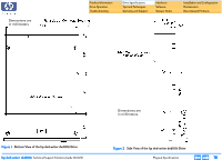
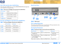
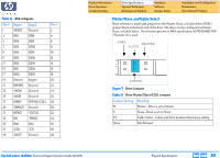
Table 12 ATA-2 Signals Pin # Signal Signal Pin # 1 -RESET Ground 2 3 DD7 DD8 4 5 DD6 DD9 6 7 DD5 DD10 8 9 DD4 DD11 10 11 DD3 DD12 12 13 DD2 DD13 14 15 DD1 DD14 16 17 DD0 DD15 18 19 Ground keypin 20 21 DMARQ Ground 22 23 -DIOW Ground 24 25 -DIOR Ground 26 27 IORDY SPSYNC/CSEL 28 29 -DMACK Ground 30 31 INTRQ -IOCS16 32 33 DA1 -PDIAG 34 35 DA0 DA2 36 37 -CS0 -CS1 38 39 -DASP Ground 40 Product Information Drive Operation Troubleshooting Drive Specifications Tips and Techniques Warranty and Support Interfaces Software Release Notes Installation and Configuration Maintenance Discontinued Products Master/Slave and Cable Select Drive selection is made with jumpers on the Master, Slave, or Cable Select (CSEL) jumper block at the back end of the drive. The drive can be configured as Master, Slave, or Cable Select. The selection process in ANSI specification X3T10/0948D ATA2 Revision 4c is used. CSEL MASTER SLAVE JUMPER Figure 7 Drive Jumpers Table 13 Drive Master/Slave/CSEL Jumpers Jumper Setting M S CS None Meaning Master - Drive is set to Master Slave - Drive is set to Slave Cable Select - Cable and drive position determines setting Not Allowed hp dvd-writer dvd100i Technical Support Solutions Guide 10/25/01 Physical Specifications ⇐ ⇒ 20
-
 1
1 -
2
-
3
-
4
-
5
-
6
-
7
-
8
-
9
-
10
-
11
-
12
-
13
-
14
-
 15
15 -
 16
16 -
 17
17 -
 18
18 -
 19
19 -
 20
20 -
 21
21 -
 22
22 -
 23
23 -
 24
24 -
 25
25 -
26
-
27
-
28
-
29
-
30
-
31
-
32
-
33
-
34
-
35
-
36
-
37
-
38
-
39
-
40
-
41
-
42
-
43
-
44
-
45
-
46
-
47
-
48
-
49
-
50
-
51
-
52
-
53
-
54
-
55
-
56
-
57
-
58
-
59
-
60
-
61
-
62
-
63
-
64
-
65
-
66
-
67
-
68
-
69
-
70
-
71
-
72
-
73
-
74
-
75
-
76
-
77
-
78
-
79
-
80
-
81
-
82
-
83
-
84
-
85
-
86
-
87
-
88
-
89
-
90
-
91
-
92
-
93
-
94
-
95
-
96
-
97
-
98
-
99
-
100
-
101
-
102
-
103
-
104
 |
 |